Reaction cavity device and substrate processing equipment with same

A technology of reaction chamber and air intake device, which is applied in the field of microelectronics, can solve problems such as waste of process gas, and achieve the effects of ensuring quality, facilitating planarization, and improving utilization rate

Active Publication Date: 2013-04-10
BEIJING NAURA MICROELECTRONICS EQUIP CO LTD
View PDF4 Cites 8 Cited by
  • Summary
  • Abstract
  • Description
  • Claims
  • Application Information

AI Technical Summary

Problems solved by technology

However, increasing the pumping capacity to quickly discharge various by-products also causes a large amount of waste of unreacted process gas

Method used


Image

  • Reaction cavity device and substrate processing equipment with same
  • Reaction cavity device and substrate processing equipment with same
  • Reaction cavity device and substrate processing equipment with same

Examples


Embodiment 1

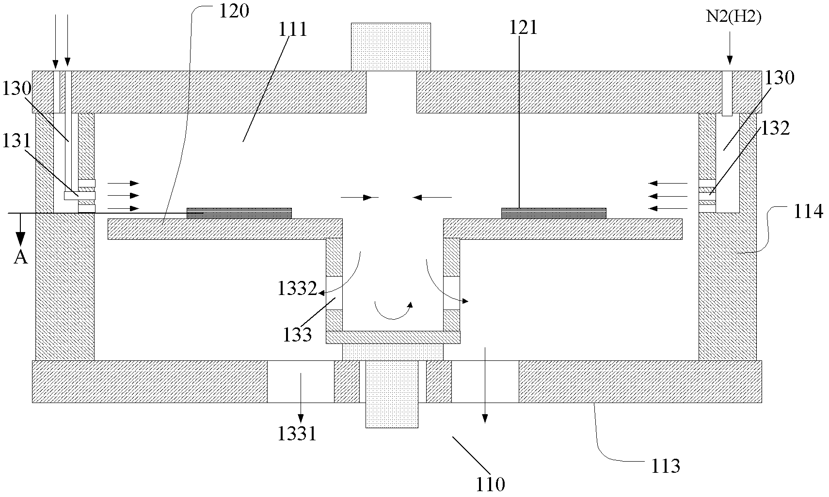
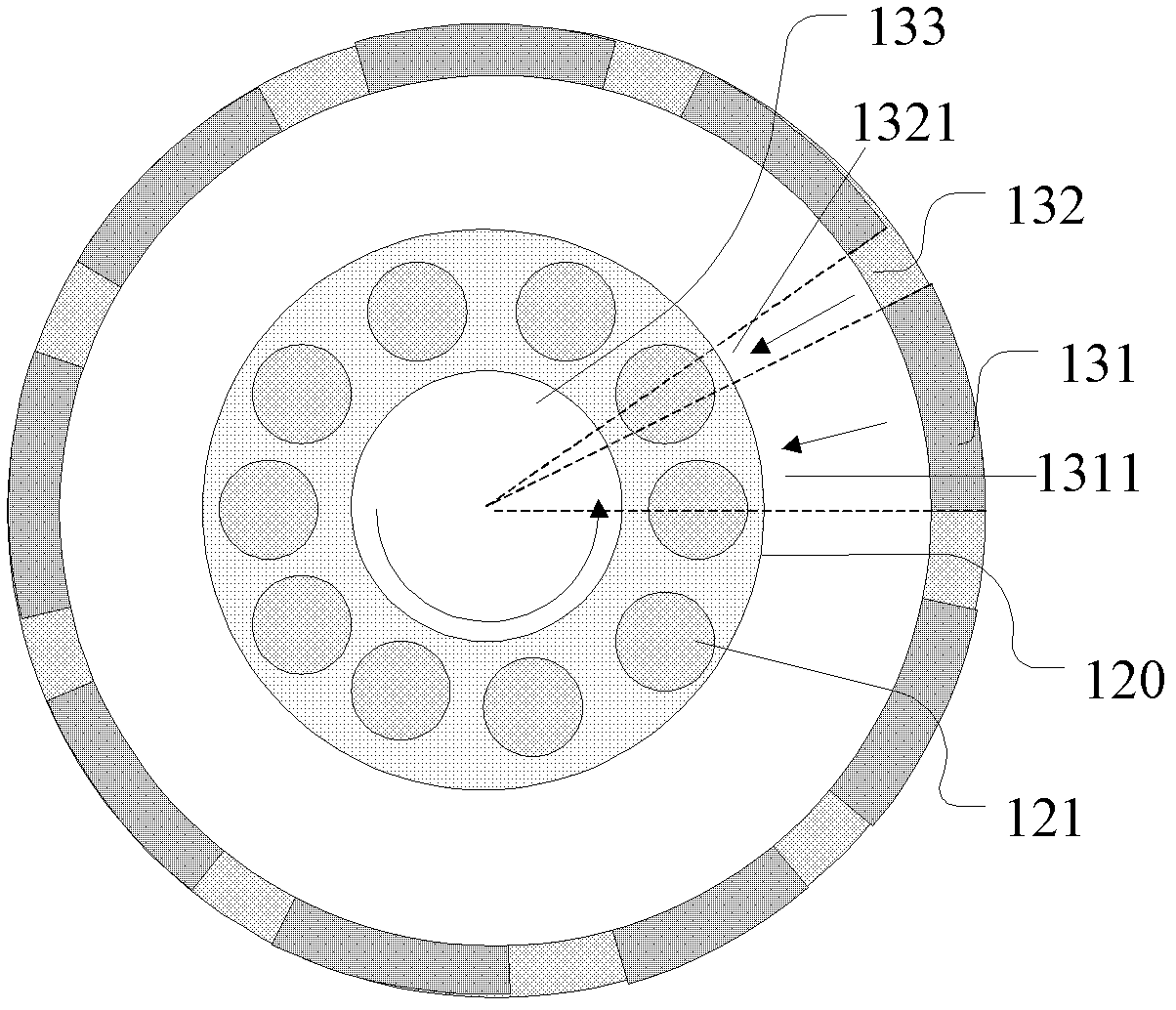
[0044] by figure 1 The reaction chamber setup shown is taken as an example for detailed description. Such as figure 1 As shown, the reaction chamber device adopts a structure with air intake around and exhaust in the center. The tray 120 on which the substrate 121 is placed is ring-shaped. combine image 3 , the substrate 121 is placed in the circumferential direction of the outer edge of the tray 120 . The tray 120 can rotate around the axial direction of the central hole of the tray 120, because the substrate 121 on the tray 120 will alternately pass through the first gas regions ( image 3 The fan-shaped area 1311 formed by the dotted line) and the area of ​​the second gas formed by the spacer gas ( image 3 The fan-shaped area 1321 composed of dotted lines in . When the substrate 121 passes through the first fan-shaped region 1311 formed by the process gas, a thin film will be deposited on the surface, and when passing through the second fan-shaped region 1321 formed...

Embodiment 2

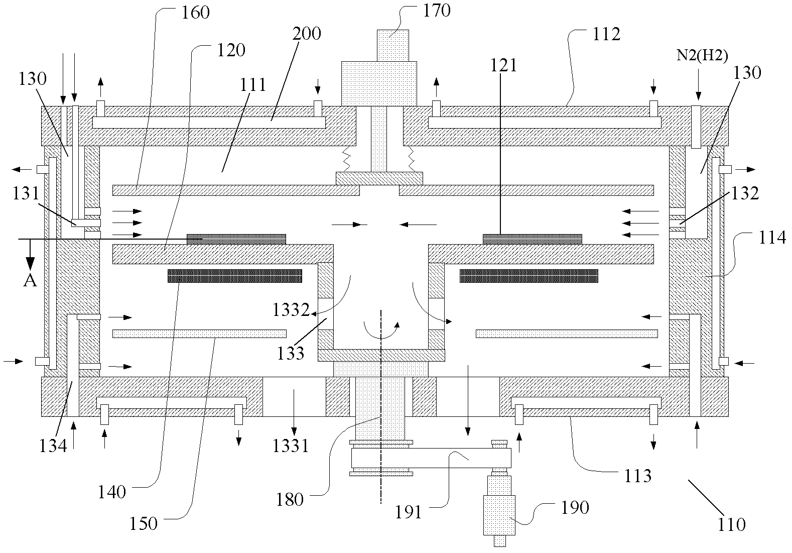
[0054] The reaction chamber device of another embodiment of the present invention is as Figure 4 shown, combined with figure 1 , For example, the process gas can also be introduced from the central hole to the surrounding. And the gas is discharged to the outside from the peripheral wall 114 of the reaction chamber device.

[0055] combine Figure 5 , as an embodiment of the present invention, the air intake assembly 130 of the air intake device can also be cylindrical in shape and arranged in the central hole of the tray 120, and the air intake assembly 130 includes alternately distributed gas nozzles 131 and other A gas nozzle 132 , wherein the process gas is sprayed into the reaction chamber from the gas nozzle 131 , and the isolation gas is injected into the reaction chamber from the gas nozzle 132 .

[0056] In one embodiment of the present invention, the reaction chamber device of the embodiment of the present invention further includes an exhaust assembly 133, and t...


PUM


Abstract

The invention provides a reaction cavity device. The reaction cavity device comprises a cavity body, a tray and a gas inlet device, wherein a reaction cavity is restricted in the cavity body, the tray is arranged in the reaction cavity and can rotate, and the gas inlet device is used for forming a first gas region and a second gas region which are mutually alternate in the cavity body; a process gas is fed into the first gas region, an isolation gas is fed into the second gas region, and a substrate on the tray alternatively passes the first gas region and the second gas region along with the rotation of the tray. The invention also provides substrate processing equipment. According to the reaction cavity device provided by the invention, the impact of byproducts generated after a reactant gas reacts on the film formation of the substrate can be effectively prevented. According to the substrate processing equipment provided by the invention, the impact of the byproducts of the reactant gas on the film formation of the substrate is reduced, process indexes for the film formation of the substrate are promoted, the utilization rate of the reaction gas can also be increased, and the utilization efficiency of the substrate processing equipment is increased.

Description

technical field [0001] The invention relates to the technical field of microelectronics, and particularly designs a reaction chamber device and substrate processing equipment with the reaction chamber device. Background technique [0002] Chemical vapor deposition (CVD) equipment is widely used in semiconductor, LED, liquid crystal and other industries. Thin films can be prepared on different types of substrate surfaces using CVD equipment. In the LED industry, MOCVD equipment (a type of CVD equipment) is generally used to produce epitaxial wafers. Before using CVD equipment to produce epitaxial wafers, it is necessary to introduce process gas into the process chamber through the gas introduction device, and make it flow through the surface of the substrate. Since the substrate has been heated to the temperature required by the process, the process gas will undergo a high-temperature chemical reaction when it flows over the surface of the substrate, and the product of the ...

Claims


Application Information

Patent Timeline
Patent Type & Authority Applications(China)
IPC IPC(8): C23C16/455H01L21/67
Inventor 周卫国
Owner BEIJING NAURA MICROELECTRONICS EQUIP CO LTD
Why Eureka
Try Eureka