Mud-and-water auto-separating pipeline apparatus

A pipeline device and self-separation technology, applied in the direction of filtration separation, separation method, fixed filter element filter, etc., can solve the problems of high energy consumption, unsuitable water for crop irrigation, complex structure, etc., and achieve the effect of low energy consumption

Inactive Publication Date: 2016-10-26
张铁耀
View PDF5 Cites 7 Cited by
  • Summary
  • Abstract
  • Description
  • Claims
  • Application Information

AI Technical Summary

Problems solved by technology

[0007] The mud-water separation equipment disclosed in this patent document has a complex structure, and the separation of sediment in the water requires a motor to provide kinetic energy for the separation drum, which consumes a lot of energy and is not suitable for crop irrigation water.

Method used


Image

  • Mud-and-water auto-separating pipeline apparatus
  • Mud-and-water auto-separating pipeline apparatus
  • Mud-and-water auto-separating pipeline apparatus

Examples


Embodiment 1

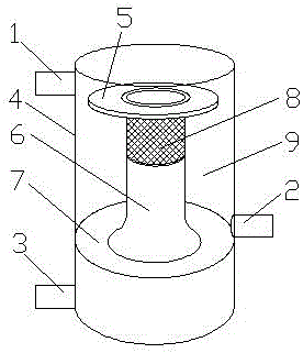
[0041] see figure 1, a mud-water self-separation pipeline device, including a water inlet pipe 1, an outlet pipe 2 and a sewage pipe 3, and also includes a mud-water self-separation component, and the mud-water self-separation component includes a cylindrical pipe body 4, and the inner side of the cylindrical pipe body 4 An annular step 5 is arranged on the wall, and an inner fixing seat 6 is arranged below the annular step 5, and an annular groove 7 is formed between the inner fixing seat 6 and the inner side wall of the cylindrical pipe body 4, and an annular groove 7 is arranged on the annular step 5. Filter screen 8, the upper end of the annular filter screen 8 is connected with the annular step 5, the lower end of the annular filter screen 8 is connected with the inner fixing seat 6, the inner side wall of the cylindrical pipe body 4 and the outer side wall of the annular filter screen 8 form a clear water chamber 9, the outlet pipe 2 communicates with the clear water cha...

Embodiment 2

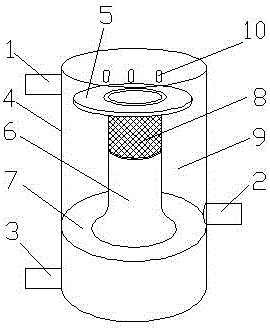
[0044] see figure 2 , a mud-water self-separation pipeline device, including a water inlet pipe 1, an outlet pipe 2 and a sewage pipe 3, and also includes a mud-water self-separation component, and the mud-water self-separation component includes a cylindrical pipe body 4, and the inner side of the cylindrical pipe body 4 An annular step 5 is arranged on the wall, and an inner fixing seat 6 is arranged below the annular step 5, and an annular groove 7 is formed between the inner fixing seat 6 and the inner side wall of the cylindrical pipe body 4, and an annular groove 7 is arranged on the annular step 5. Filter screen 8, the upper end of the annular filter screen 8 is connected with the annular step 5, the lower end of the annular filter screen 8 is connected with the inner fixing seat 6, the inner side wall of the cylindrical pipe body 4 and the outer side wall of the annular filter screen 8 form a clear water chamber 9, the outlet pipe 2 communicates with the clear water c...

Embodiment 3

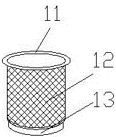
[0049] see Figure 2-Figure 4 , a mud-water self-separation pipeline device, including a water inlet pipe 1, an outlet pipe 2 and a sewage pipe 3, and also includes a mud-water self-separation component, and the mud-water self-separation component includes a cylindrical pipe body 4, and the inner side of the cylindrical pipe body 4 An annular step 5 is arranged on the wall, and an inner fixing seat 6 is arranged below the annular step 5, and an annular groove 7 is formed between the inner fixing seat 6 and the inner side wall of the cylindrical pipe body 4, and an annular groove 7 is arranged on the annular step 5. Filter screen 8, the upper end of the annular filter screen 8 is connected with the annular step 5, the lower end of the annular filter screen 8 is connected with the inner fixing seat 6, the inner side wall of the cylindrical pipe body 4 and the outer side wall of the annular filter screen 8 form a clear water chamber 9, the outlet pipe 2 communicates with the clea...


PUM


Abstract

The invention discloses a mud-and-water auto-separating pipeline apparatus and belongs to the technical field of water conservancy transportation pipelines. The pipeline apparatus includes a water inlet pipe, a water outlet pipe and a drainage pipe and also includes a mud-and-water auto-separating part. The mud-and-water auto-separating part includes a cylindrical pipe body, wherein annular steps are formed on an inner side wall of the cylindrical pipe body. An inner fixing base is arranged under the annular steps. An annular groove is formed by the inner fixing base and the inner side wall of the cylindrical pipe body. An annular filter screen is disposed on the annular steps, wherein the top end of the annular filter screen is connected to the annular steps and the bottom end of the annular filter screen is connected to the inner fixing base. A clear water chamber is formed by the inner side wall of the cylindrical pipe body and an outer side wall of the annular filter screen. The water outlet pipe is communicated with the clear water chamber. The water inlet pipe is arranged on the side wall of the cylindrical pipe body and is arranged above the annular steps. The pipeline apparatus can automatically separate mud from water, wherein clear water flows out through the water outlet pipe while a mud and sand mixture is discharged through the drainage pipe. The pipeline apparatus is free of extra kinetic energy, is low in energy consumption and is suitable for agricultural irrigation.

Description

technical field [0001] The invention relates to the technical field of water conservancy transportation pipelines, in particular to a mud-water self-separating pipeline device. Background technique [0002] With the industrialization of modern agriculture, the irrigation of crops gradually tends to be regular and quantitative. In the past, the way of irrigating crops only by rainwater is increasingly unable to meet the development needs of modern agriculture. In order to change these conditions, people have developed the use of water storage tanks for irrigation of crops. [0003] Water storage tanks are the main water storage equipment for modern agricultural irrigation and drinking water. Rainwater is natural water, which belongs to soft water, does not contain limestone, is very pure, and is very suitable for crop irrigation after simple treatment. But rainwater evaporates easily when exposed to the air, especially in arid regions. At present, there are many ways to u...

Claims


Application Information

Patent Timeline
Patent Type & Authority Applications(China)
IPC IPC(8): B01D29/11
CPCB01D29/117
Inventor 张铁耀赵天润樊军
Owner 张铁耀
Why Eureka
Try Eureka