

Stirling cooling storage
A technology of cooling storage and refrigerant, applied in the field of Stirling cooling storage, can solve the problems of noise piping damage, etc., and achieve the effect of preventing condensation
- Summary
- Abstract
- Description
- Claims
- Application Information
AI Technical Summary
Problems solved by technology
Method used
Image

Examples
Embodiment approach 1
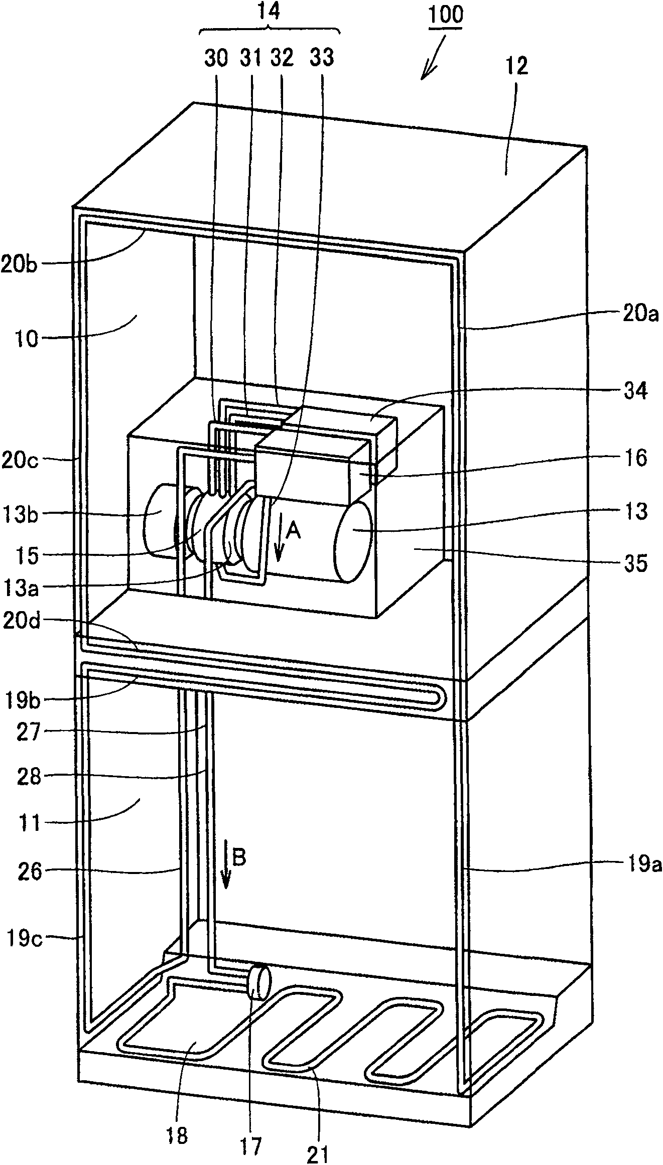
[0027] figure 1 It is a perspective view showing a schematic structure of the Stirling cooler 100 according to Embodiment 1 of the present invention, as shown in figure 1 As shown, the Stirling cooler 100 has: a refrigerator compartment (cooling compartment) 10 for accommodating an object to be refrigerated (object to be cooled); a freezer compartment ( cooling compartment) 11; a casing (partition wall) 12 made of a heat insulating material that divides the freezing compartment 11 and the refrigerating compartment 10; and a Stirling refrigerator 13 including a heat dissipation portion 13a and a heat absorption portion 13b. In addition, the Stirling cooler 100 also has: a secondary refrigerant circulation circuit 14 in which the heat supply medium (secondary refrigerant) A naturally circulates; an evaporator 15 that evaporates the heat medium A to cool the heat dissipation portion 13a; The tertiary refrigerant circulation circuit 28 through which the heating medium (tertiary r...
Embodiment approach 2
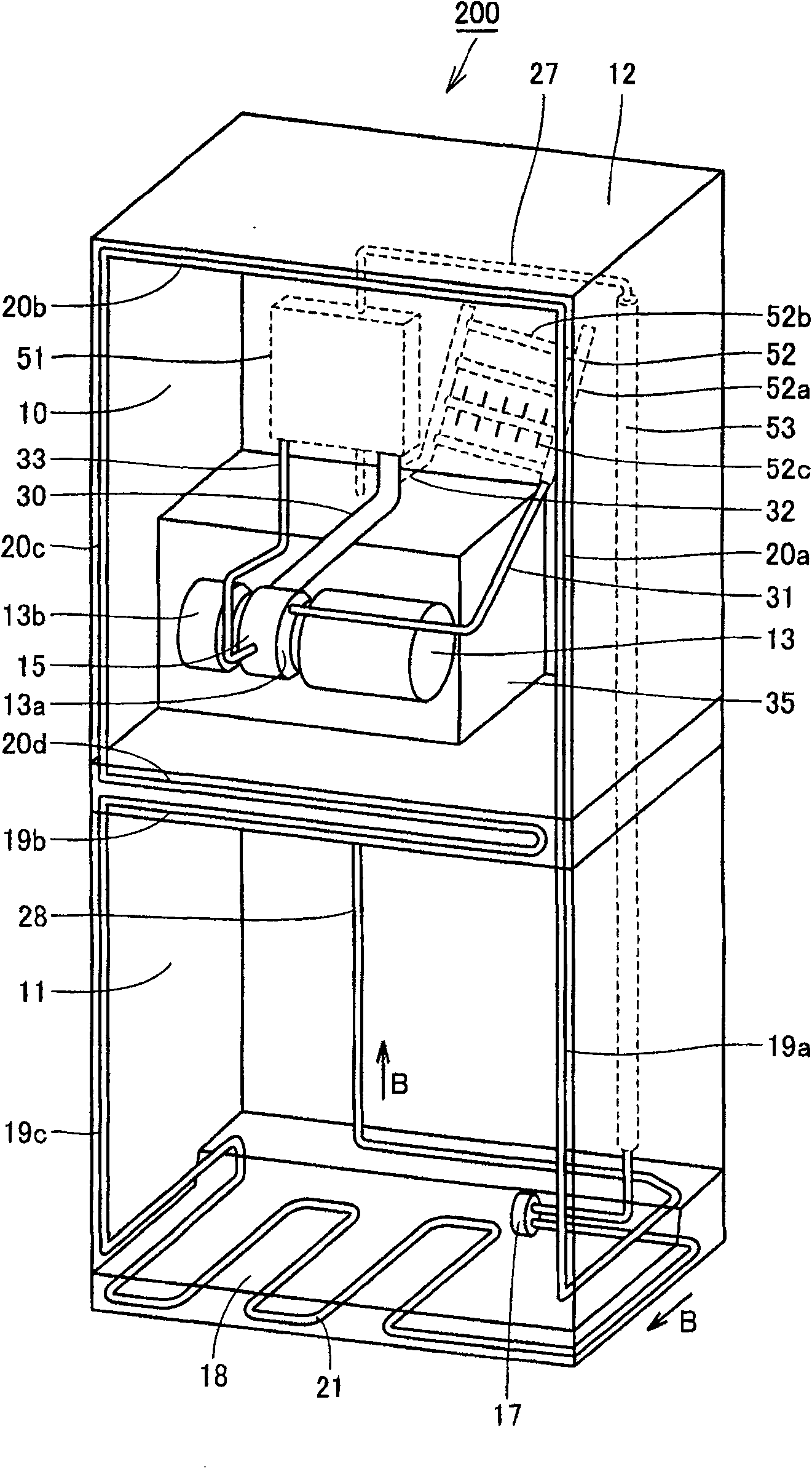
[0043] combine Figure 3 to Figure 5 Embodiment 2 of the present invention will be described. image 3 It is a perspective view of the Stirling cooler 200 of the second embodiment, as image 3 As shown, the heat exchanger 51 and the condenser 52 are installed on the rear side of the Stirling cooler 200 . In addition, suction tank 53 is provided on one side of the back side of Stirling cooler 200 . The suction tank 53 is configured in a columnar shape, extends from the upper surface side toward the lower surface side of the Stirling cooler 200 , and is embedded in the casing 12 made of a heat insulating material.
[0044] In addition, the suction tank 53 has a larger diameter than the high-temperature pipe 27 and the like connected to the upper end portion of the suction tank 53 . In addition, the lower end of the suction tank 53 is located on the bottom side of the Stirling cooler 200 , and the piezoelectric pump 17 is connected to the lower end of the suction tank 53 . In...
Embodiment approach 3
[0057] combine Figure 6 Embodiment 3 of the present invention will be described. Figure 6 It is a piping system diagram of the Stirling cooler 300 according to Embodiment 3, such as Figure 6As shown, the evaporator 15 is provided with a double-tube heat exchanger 80 having the functions of a condenser and a heat exchanger, which is arranged above the evaporator 15 . This double-tube heat exchanger 80 has an outer tube 81 and an inner tube 82 formed with a smaller diameter than the outer tube 81 and disposed inside the outer tube 81 . A plurality of cooling fins 83 are provided on the outer peripheral surface of the outer tube 81 . In addition, the secondary refrigerant circulation circuit 14 is connected between the outer pipe 81 and the inner pipe 82 , and the tertiary refrigerant circulation circuit 28 is connected to the inner pipe 82 . That is, between the outer tube 81 and the inner tube 82 at the upper end of the double-tube heat exchanger 80, the gas tube 30 of th...
PUM
 Abstract
Description
Claims
Application Information