Wall finding for wireless lighting assignment

A technology of wireless communication and partition wall, which is applied in the direction of radio wave measurement system, lighting device, measuring device, etc., and can solve the problem of not specifically solving the problem of assigning lighting nodes to switch control nodes

Inactive Publication Date: 2008-03-05
KONINKLIJKE PHILIPS ELECTRONICS NV
View PDF2 Cites 10 Cited by
  • Summary
  • Abstract
  • Description
  • Claims
  • Application Information

AI Technical Summary

Problems solved by technology

[0005] A large number of prior technical documents (such as WO 01/97466, and Patwari et al.: "RelativeLocation Estimation in Wireless Sensor Networks", IEEE Transactions on Signal Processing, vol.51, no.8, Au

Method used


Image

  • Wall finding for wireless lighting assignment
  • Wall finding for wireless lighting assignment
  • Wall finding for wireless lighting assignment

Examples


Embodiment Construction

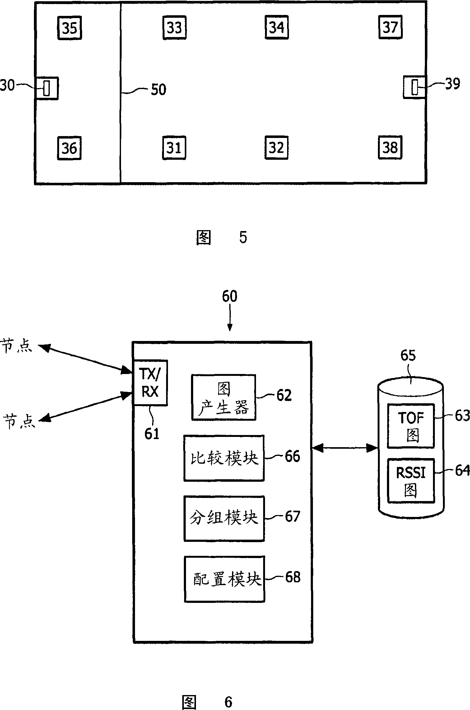
[0023] A number of techniques are available for determining the spatial location of wirelessly connected nodes in a network. One example is the signal "time of flight" (ToF) method, where the time it takes for a signal to pass between nodes is used to estimate the distance between nodes. This provides a very accurate estimate of the distance between nodes and is relatively immune to physical obstruction between signaling nodes. Therefore, this is a common method for determining distances between nodes. An alternative technique is to use Received Signal Strength Indication (RSSI) measurements to provide an estimate of the distance between two nodes. Because received signal strength decreases with distance, the RSSI reading turns into an actual estimate of distance.

[0024] RSSI technology is slightly less accurate than ToF ranging and is usually less used for automatic position detection. A characteristic of RSSI ranging is that it is subject to absorption and dispersion by...


PUM


Abstract

A method for determining the location of partition walls within a building uses a wirelessly interconnected network of nodes to determine relative spatial positions of selected nodes using (i) received signal strength indication (RSSI) values and time of flight (ToF) values, both indicative of a distance of separation between two communicating nodes. A first map of the network topology is derived from the RSSI values and a second map of the network topology is derived from the ToF values. The RSSI values are affected by building partition walls whereas the ToF values are relatively unaffected by partition walls. A comparison of the first and second maps is used to determine the location of partition walls within the building.

Description

technical field [0001] The present invention relates to a method and apparatus for managing wireless lighting nodes in a building, in particular to assigning each of several lighting nodes or luminaires to a respective switch control node. Background technique [0002] The use of wirelessly controlled lighting units or luminaires (hereinafter referred to as light nodes) in buildings is becoming more and more common, as this can substantially reduce lighting installation costs. The physical wiring between the lighting switch or activation sensor (hereinafter referred to as the switch control node) and the lighting node is replaced by a wireless (eg radio) connection. All lighting nodes and switching control nodes only need to be connected to appropriate power sources and do not need electrical connections. Each luminaire includes a wireless receiver and each switch control node includes a wireless transmitter. During management, each luminaire is identified and assigned to ...

Claims


Application Information

Patent Timeline
IPC IPC(8): H05B37/02G01S5/02
CPCH05B37/0272G01S5/0289H05B37/02G01S5/02H05B47/10H05B47/19G01S5/013H05B33/00
Inventor S·M·比特彻斯P·R·西蒙斯
Owner KONINKLIJKE PHILIPS ELECTRONICS NV
Why Eureka
Try Eureka