
Control device for thread gripper of sewing machine

A technology of a control device and a thread gripper, which is applied to the sewing machine control device, sewing equipment, sewing machine components, etc., can solve the problems that the suture cannot reach the tension force, the use stability is poor, the spring elasticity is weakened, etc., and the working stability is achieved. High, good use effect, high practical effect

Inactive Publication Date: 2008-03-12
ZHEJIANG ZOJE SEWING MACHINE
View PDF0 Cites 9 Cited by
  • Summary
  • Abstract
  • Description
  • Claims
  • Application Information

AI Technical Summary

Problems solved by technology

It can be seen that the elastic force of the spring may be weakened after a period of use, and accordingly the suture cannot reach the corresponding tension, so its use stability is poor
Moreover, adjusting the tension of the spring is completely manual operation, which is very inconvenient in actual use

Method used


Image

  • Control device for thread gripper of sewing machine
  • Control device for thread gripper of sewing machine
  • Control device for thread gripper of sewing machine

Examples


Embodiment Construction

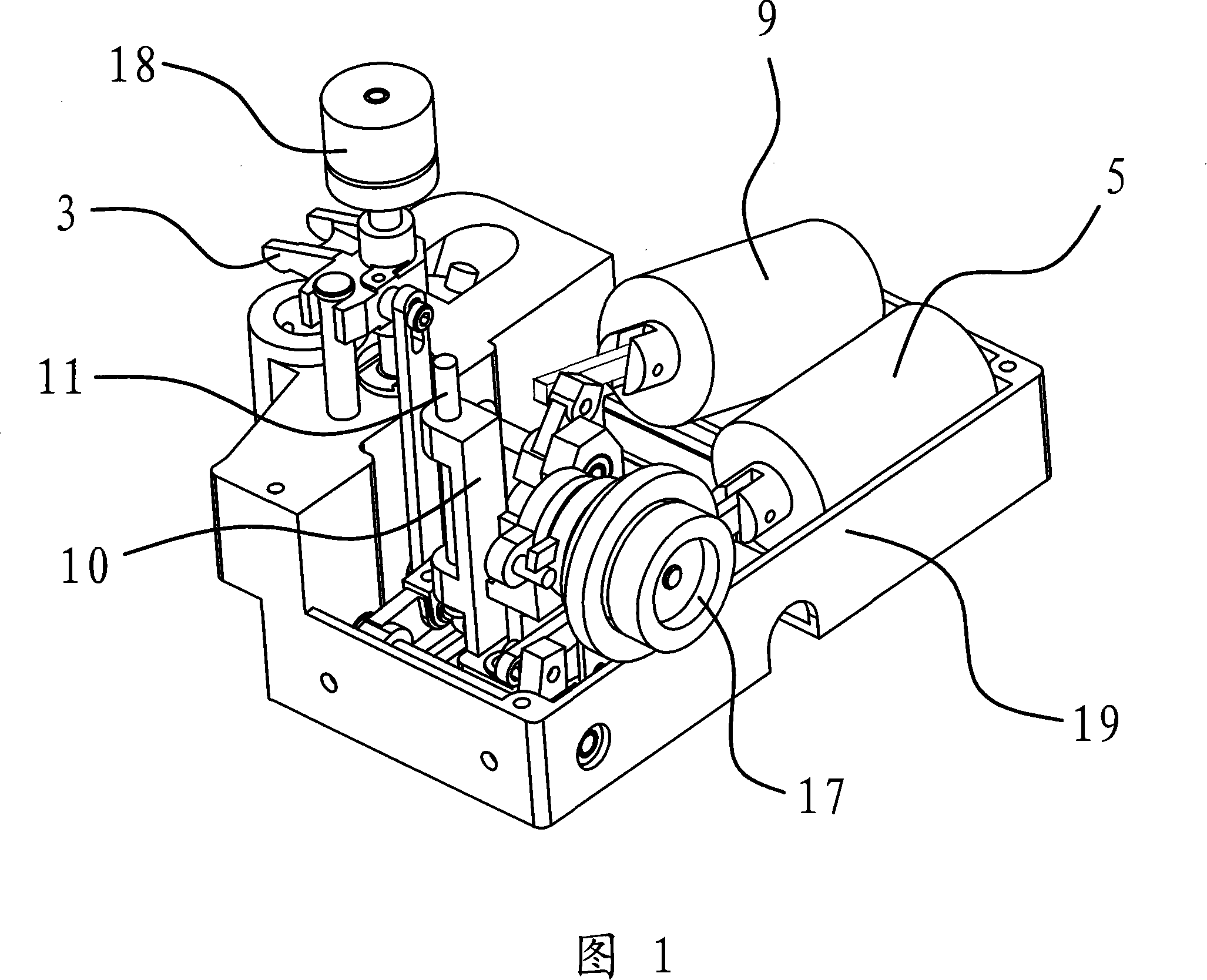
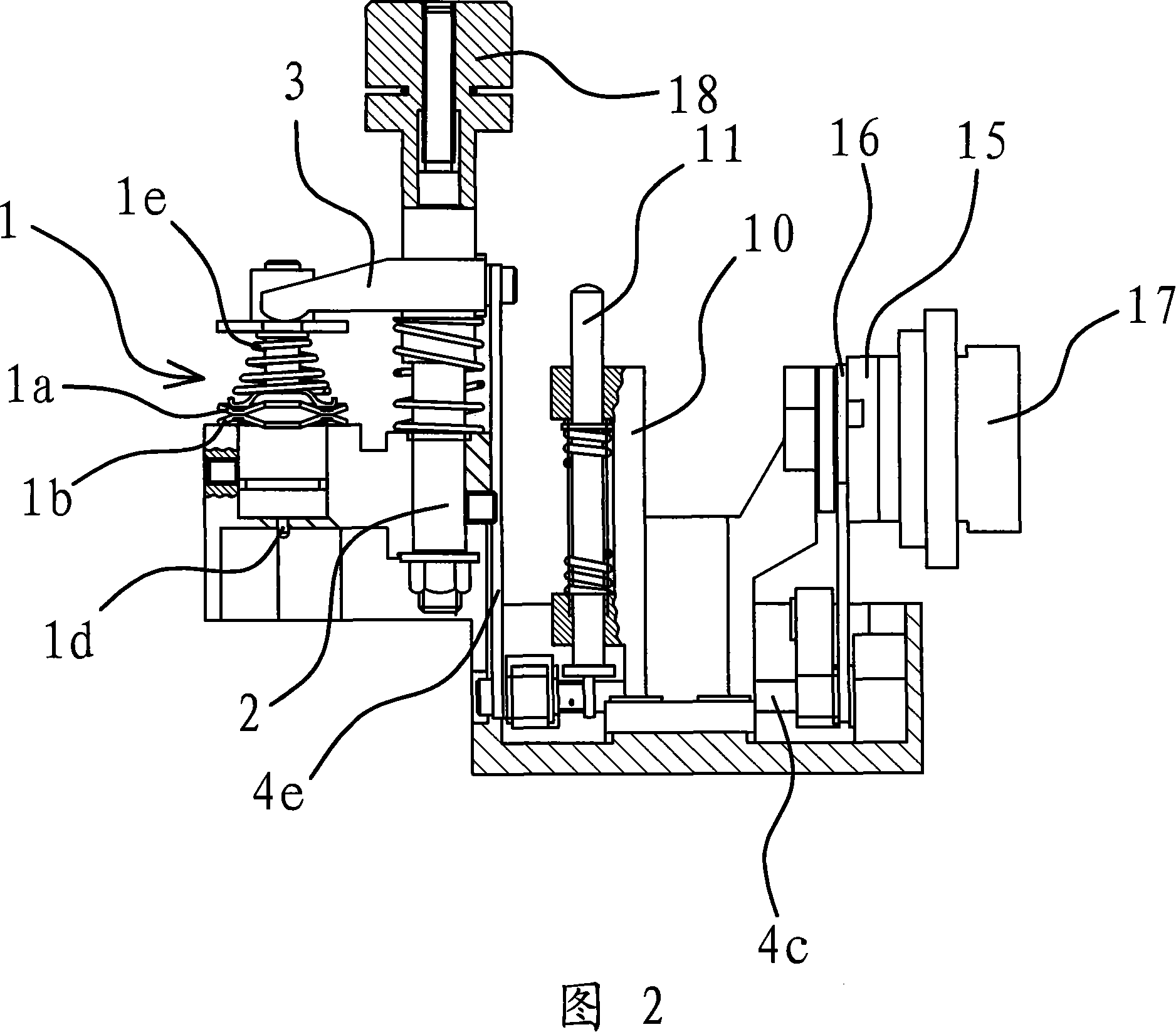
[0036] As shown in Figures 1 and 2, a thread clamp 1 is connected to the housing 19 on the sewing machine, through which the tension of the suture during the sewing process can be controlled.

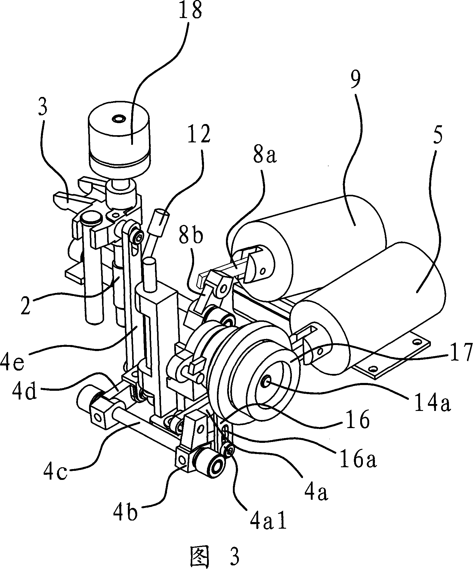
[0037]As shown in Figure 2, the thread clamp 1 includes a rod body 1c, an upper chuck 1a, a lower chuck 1b, and a spring 1e sleeved on the rod body 1c, the rod body 1c is cylindrical, and a core rod 1d is arranged inside the rod body 1c . Under the elastic force of the spring 1e, the upper chuck 1a and the lower chuck 1b are in close contact with each other. The inner end of the core rod 1d abuts on the above-mentioned upper chuck 1a, and the outer end of the core rod 1d protrudes from the rod body 1c and is located at the bottom of the upper chuck 1a and the lower chuck 1b. The control device of the thread clamp in this sewing machine is just arranged on the side of the thread clamp 1, and the thread clamp 1 can be loosened or tightened by this control device.

[0038] As shown in FI...


PUM


Abstract

The invention provides a tension disco control device in sewing machines and belongs to the field of mechanical technology. The invention resolves the following problems in tension disco control devices in prior sewing machines: Rather short service life, rather poor working stability and so on. The tension disco control device for sewing machines is arranged on one side of a tension disco; the tension disco comprises a bar body and an upper clamp disk, a lower clamp disk and a spring that are sleeved on the bar body; the control device also comprises a guide bar fixed in a casing and arranged in parallel with the bar body; the guide bar is connected with a push block that can slide vertically along the guide bar; the push block contacts with the upper clamp disk, so that the upper clamp disk can be tightly pressed on the lower clamp disk; the push block is connected with a power device I through a connection link mechanism I; besides, the casing inside is also linked to a rotation shaft; the rotation shaft is fixed with a handling part; the handling part contacts with the external end of a core bar; the handling part is connected with a power divice II through a connection link mechanism II. Due to the two power devices, the control device has advantages of rather long service life, high working stability and diversified operation and etc.

Description

technical field [0001] The invention belongs to the technical field of machinery, and relates to a sewing machine, in particular to a control device for a thread clamp in the sewing machine. Background technique [0002] There is a thread gripper for clamping the suture in the sewing machine, by which the tension force of the suture in the sewing process of the sewing machine can be adjusted. The thread clamp includes a cylindrical rod body, an upper chuck, a lower chuck, and a spring sleeved on the rod body, and the upper chuck and the lower chuck are tightly attached to each other under the elastic force of the spring. A core rod is arranged in the body of the rod, the inner end of the core rod pushes against the above-mentioned upper chuck, and the outer end of the core rod protrudes from the rod body and is located at the bottom of the upper chuck and the lower chuck. [0003] The suture passes between the above-mentioned upper chuck and the lower chuck, and the elastic...

Claims


Application Information

Patent Timeline
IPC IPC(8): D05B47/04D05B69/00
Inventor 佐藤秀一陈栩华沈勇国严海军
Owner ZHEJIANG ZOJE SEWING MACHINE
Learn More