X-ray CT test system and CTmethod for testing objects

A technology for inspection equipment and X-rays, applied in X-ray equipment, material analysis using radiation, material analysis using wave/particle radiation, etc., to achieve the effect of simple mechanical structure, simple method, and simple mechanical structure

Inactive Publication Date: 2008-03-12
YXLON INT X RAY
View PDF0 Cites 7 Cited by
  • Summary
  • Abstract
  • Description
  • Claims
  • Application Information

AI Technical Summary

Problems solved by technology

This results in disadvantages with regard to the structural size of the entire testing device and with regard to the achievable measurement times

Method used


Image

  • X-ray CT test system and CTmethod for testing objects
  • X-ray CT test system and CTmethod for testing objects

Examples


Embodiment Construction

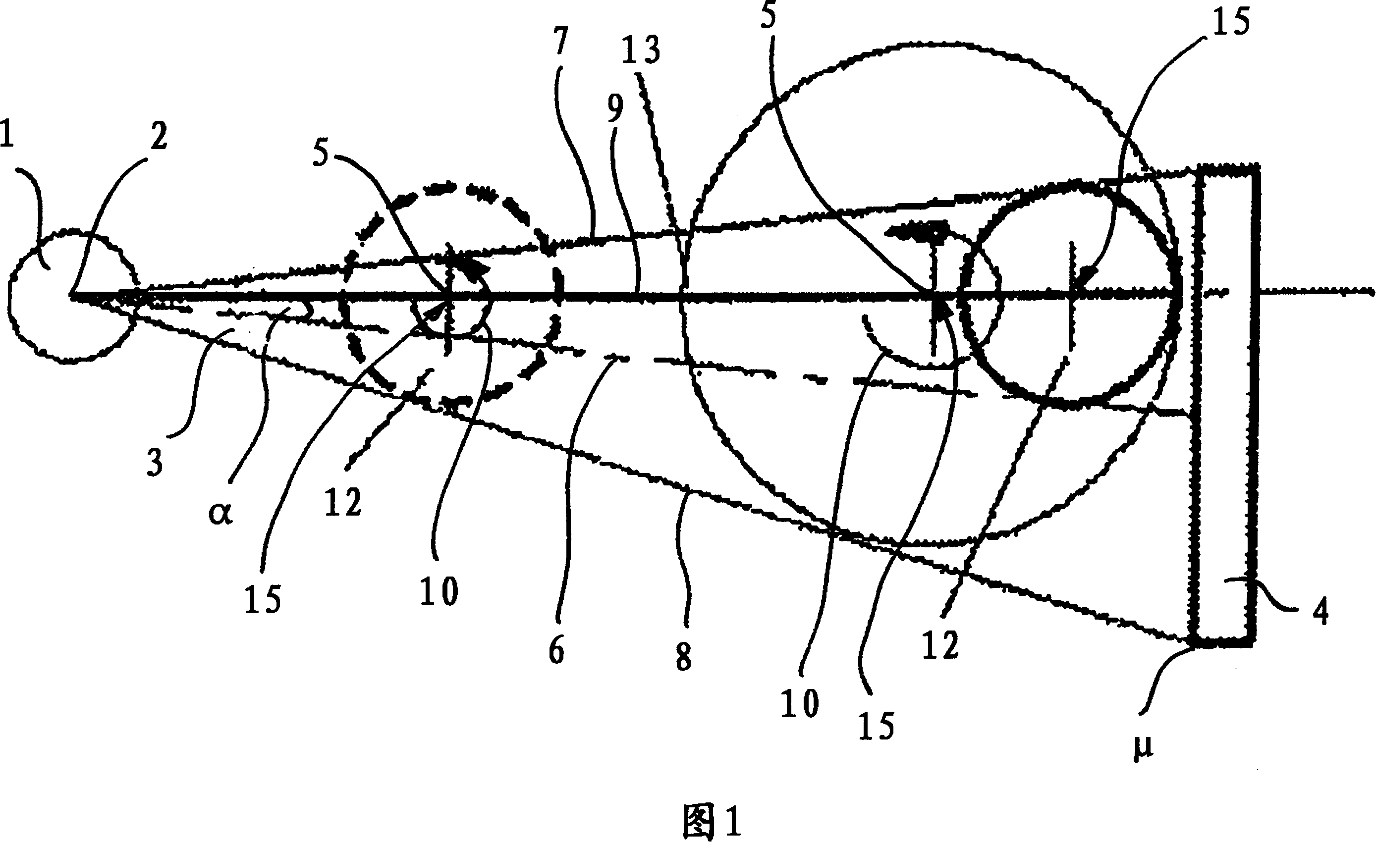
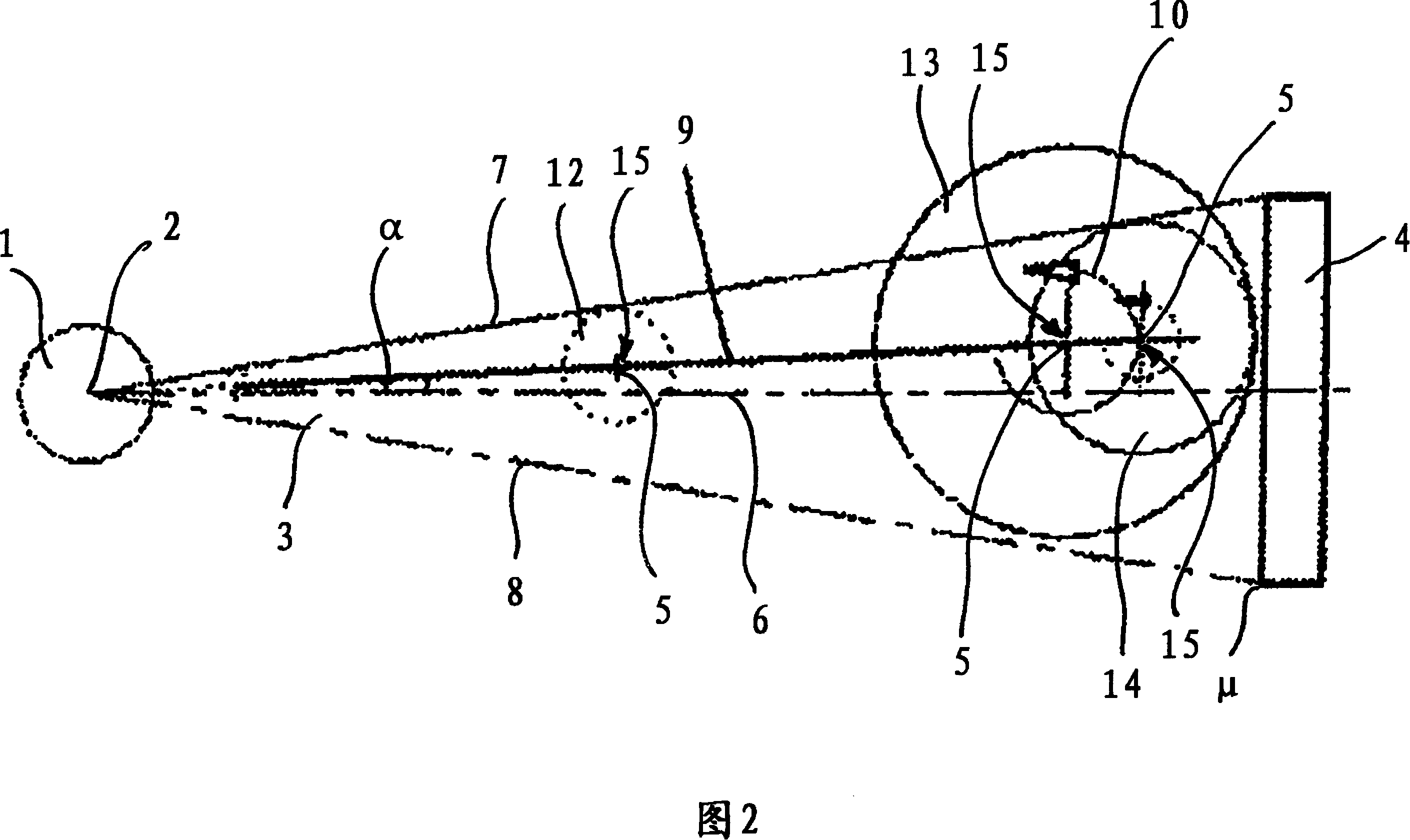
[0025] For the two exemplary embodiments below, it is assumed that the fan beam 3 is present. Of course, these embodiments are also similarly suitable for cone beams, which is immediately comprehensible for the skilled person, because the skilled person knows in principle the different geometries of the device and can easily learn from the The embodiment with the fan beam 3 is transferred to the cone beam.

[0026] FIG. 1 schematically shows a plan view of an X-ray CT inspection system. The x-ray tube 1 has a focal point 2 from which an x-ray beam emerges in the form of a fan beam 3 . This fan beam 3 strikes a detector 4 which is completely illuminated by the fan beam 3 . Such arrangements are sufficiently known in industrial CT. The distance between detector 4 and focal point 2 can be varied in order to achieve the best possible projection geometry of the object to be examined. Since only slices of the object to be examined in the plane of the fan beam 3 can be tomographi...


PUM

PropertyMeasurementUnit
angleaaaaaaaaaa

Abstract

The present invention relates to a X ray CT examining device which is provided with a X ray tube with focus and an examining carriage that is used for accommodating the object to be checked, the X ray tube generates fan beam or conical beam, the beam totally irradiate the detector which is separated from the focus for a certain distance, the examining carriage is provided with a rotary rotation axis which is perpendicular to the plane of the fan beam or perpendicular to the central axis of the conical beam. According to the invention an examining carriage which can be fixed to at least one measuring point is arranged, wherein each checking point is arranged with the mode that the rotation axis lies in the measuring line which comes out from the focus and is clamped for a slope angle to the fan beam of the conical beam. Besides, the invention also relates to a CT method for examining the object, especially the object with different dimension with the X ray CT examining device of the invention.

Description

technical field [0001] The invention relates to an X-ray CT examination device having an x-ray tube with a focal point and an examination carriage (Pruefschlitten) for accommodating an object to be examined, the x-ray tube generating a fan-shaped beam or a cone The beam illuminates a detector at a defined distance from the focal point, while the inspection carriage has a rotatable axis of rotation which is perpendicular to the plane of the fan beam or to the central axis of the cone beam. Furthermore, the invention relates to a CT method for examining objects, in particular objects of different sizes, by means of the above-mentioned x-ray CT examination system. Background technique [0002] Two inspection methods are commonly used in industrial computed tomography (CT). One method involves translation-rotation-tomography (second generation) and the other method involves fan-beam-tomography (third generation). In both cases, the fan beam fades out before the focal spot, foc...

Claims


Application Information

Patent Timeline
Patent Type & Authority Applications(China)
IPC IPC(8): G01N23/04H05G1/02
CPCG01N23/046G01N2223/419
Inventor 马丁·蒙克费萨尔·拉克尔马蒂亚斯·黑林
Owner YXLON INT X RAY
Why Eureka
Try Eureka