Flight control system

A technology of flight control system and aircraft, applied in control/adjustment system, aircraft, non-electric variable control and other directions, can solve the problem of taking a long time, and achieve the effect of reducing the shift of sight

Inactive Publication Date: 2008-03-12
YAMAHA MOTOR CO LTD
View PDF1 Cites 33 Cited by
  • Summary
  • Abstract
  • Description
  • Claims
  • Application Information

AI Technical Summary

Problems solved by technology

There are situations where the autonomous control system takes a long time to correct the flight path

Method used


Image

  • Flight control system
  • Flight control system
  • Flight control system

Examples


Embodiment Construction

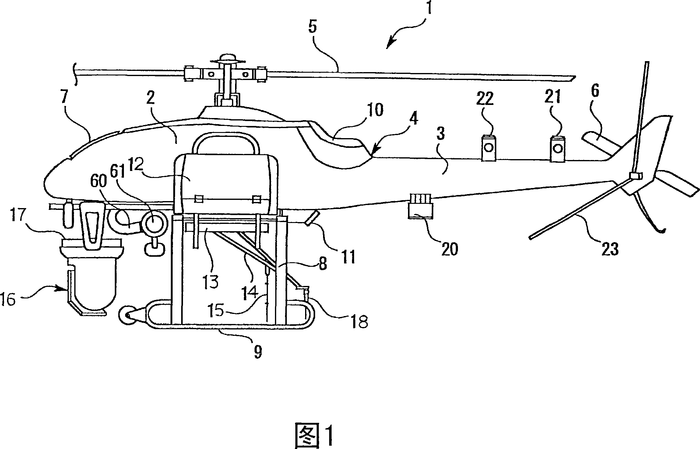
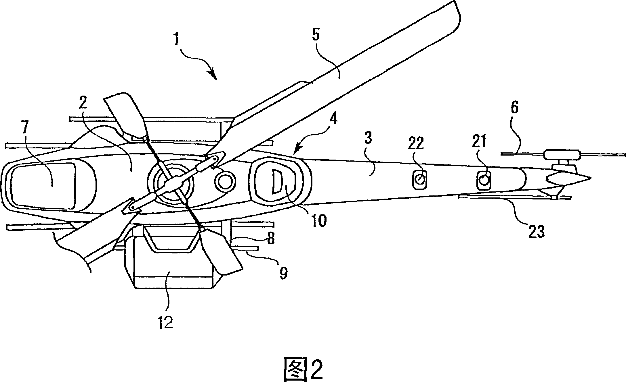
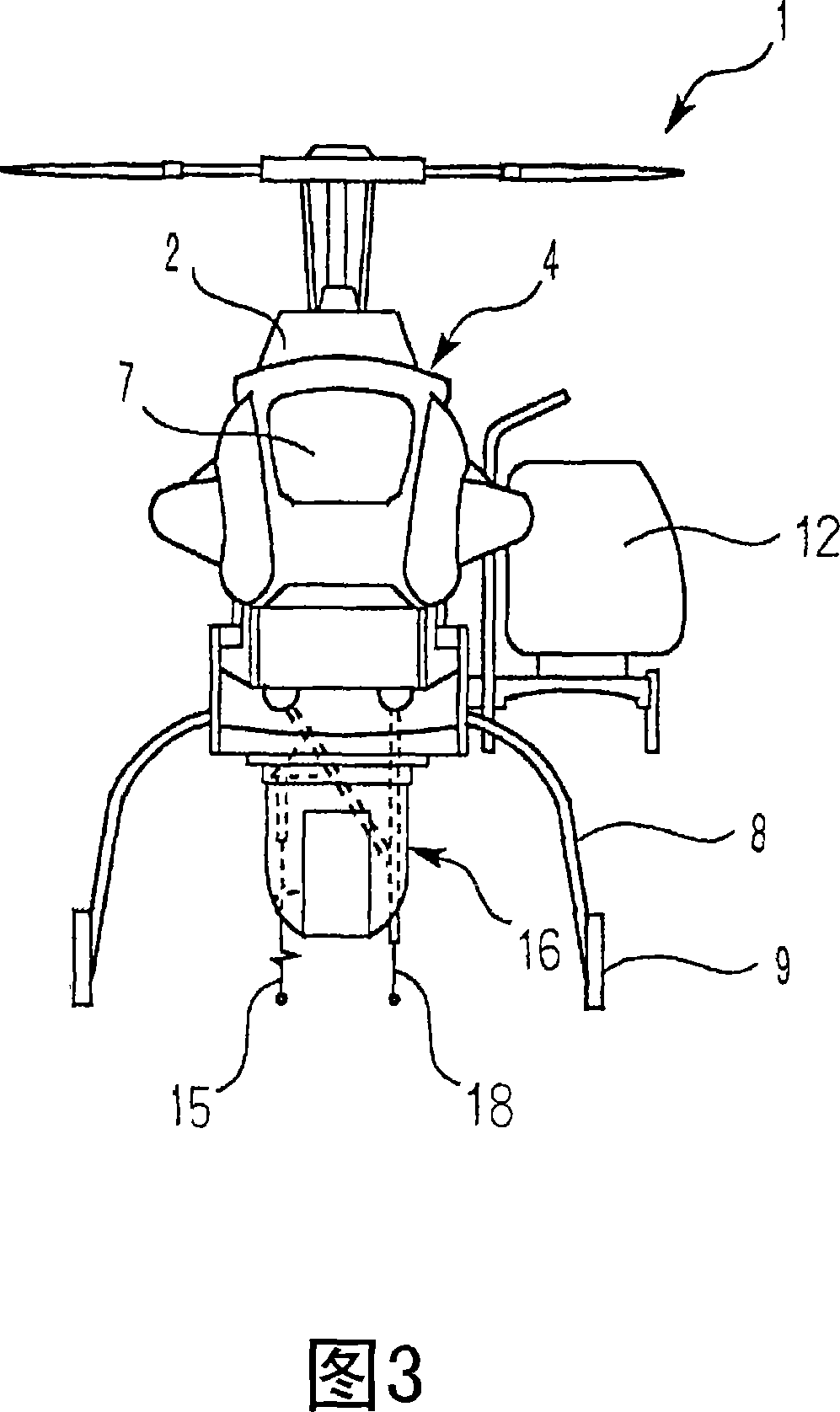
[0025] Embodiments of the flight control system according to the present invention will be described in detail below with reference to FIGS. 1-6 . 1-3 show a helicopter as an example of an aircraft according to the invention, illustrating an unmanned helicopter provided with a camera arrangement for recording aerial photographs.

[0026] The helicopter 1 has a fuselage 4 including a main body 2 and a tail body 3 . The main rotor 5 is arranged on the upper part of the main body 2 , and the tail rotor 6 is arranged on the rear of the tail body 3 . The radiator 7 is arranged at the front of the main body 2, and the engine, the air intake system, the main rotor shaft and the fuel tank are sequentially housed in the main body 2 behind it. Large-capacity fuel tanks are housed near the center of the fuselage, eliminating the need for external sub-tanks. Via support legs 8 , slide plates 9 are provided at left and right portions below the main body 2 arranged substantially at the ce...


PUM


Abstract

A flight control system has a flying body (1) and a ground station (40) that can communicate with each other. A fuselage of the flying body and a payload device are controlled from the ground station. The flying body (1) transmits data on conditions of the fuselage, flight, and the payload device to the ground station (40). The ground station (40) has a monitor screen (56) that can simultaneously display an operation panel and all the data sent from the flying body.

Description

technical field [0001] The present invention relates to a flight control system of an aircraft, in particular to a flight control system of an aircraft capable of communicating between an unmanned helicopter and a base station on land for spreading agricultural fertilizers, etc., or for installing a camera device to record images from the air. Background technique [0002] Typically, radio-controlled unmanned helicopters are used to disperse agricultural fertilizers from the air or to record aerial images or video. For example, as disclosed in JP-A-2004-268737, conventional unmanned helicopters of the above-mentioned type include so-called autonomous control type unmanned helicopters, which can use GPS (Global Positioning System) out of the operator's line of sight flight. For example, this kind of autonomous control unmanned helicopter is used in areas where manned helicopters are difficult to access, such as volcanoes and disaster-stricken areas. [0003] Usually, the at...

Claims


Application Information

Patent Timeline
Patent Type & Authority Applications(China)
IPC IPC(8): B64D45/00B64D43/00B64D47/08A01M7/00
CPCB64C2201/024G05D1/0094B64C2201/127B64C2201/108A01M7/0089G05D1/0044B64C39/024B64C2201/146G05D1/0038B64U30/20B64U2101/30B64U2201/20B64U10/17A01M7/00B64D43/00B64U10/10
Inventor 柴田英贵
Owner YAMAHA MOTOR CO LTD
Why Eureka
Try Eureka