Grinding polishing machine
A technology of polishing machine and eccentric structure, which is applied in the direction of grinding/polishing equipment, parts of grinding machine tools, grinding machines, etc., can solve the problems of inconvenient operation and low efficiency of polishing and grinding equipment, and achieve shortening time, improving grinding and polishing efficiency, compact effect
- Summary
- Abstract
- Description
- Claims
- Application Information
AI Technical Summary
Problems solved by technology
Method used
Image

Examples
Embodiment 1
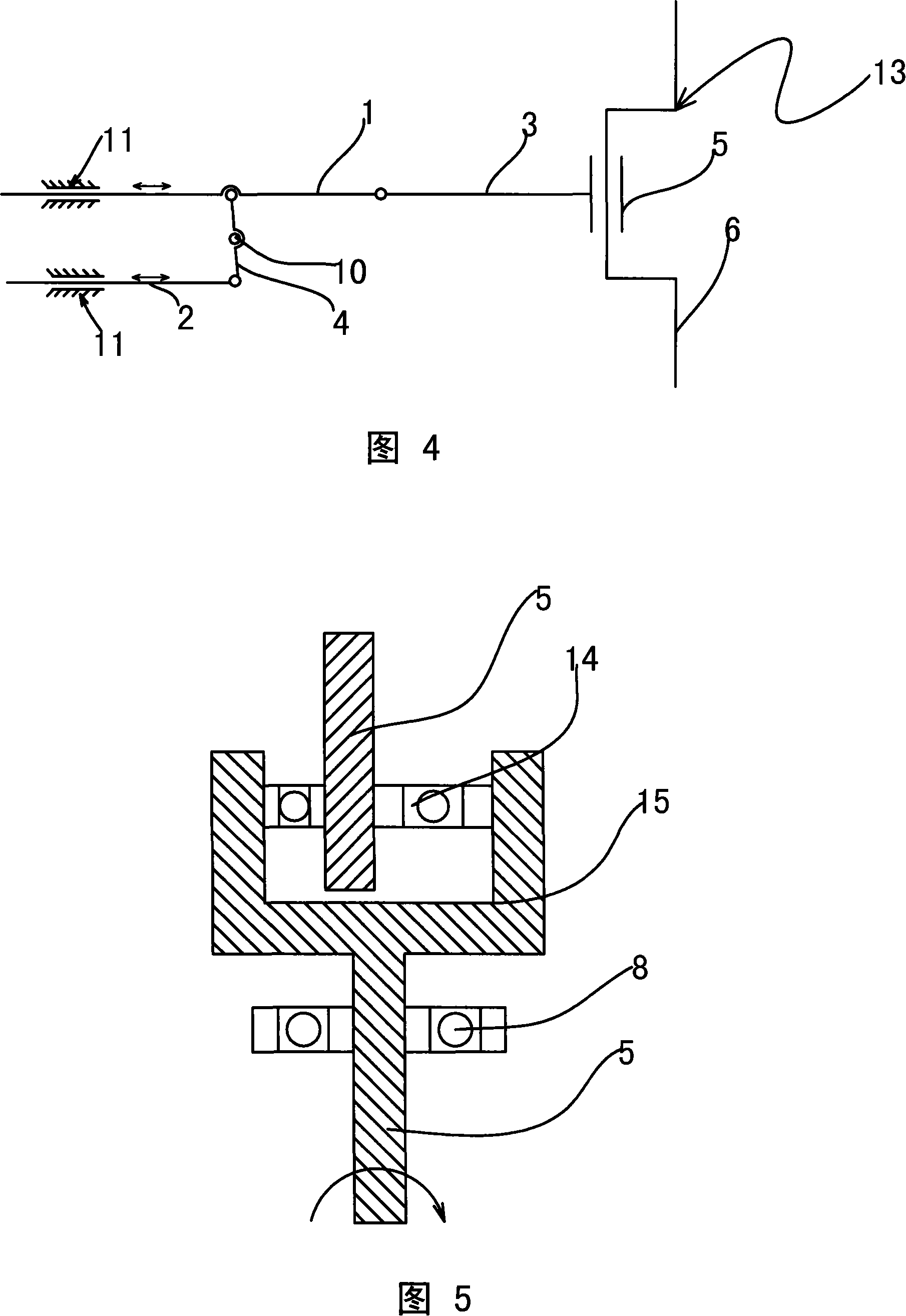
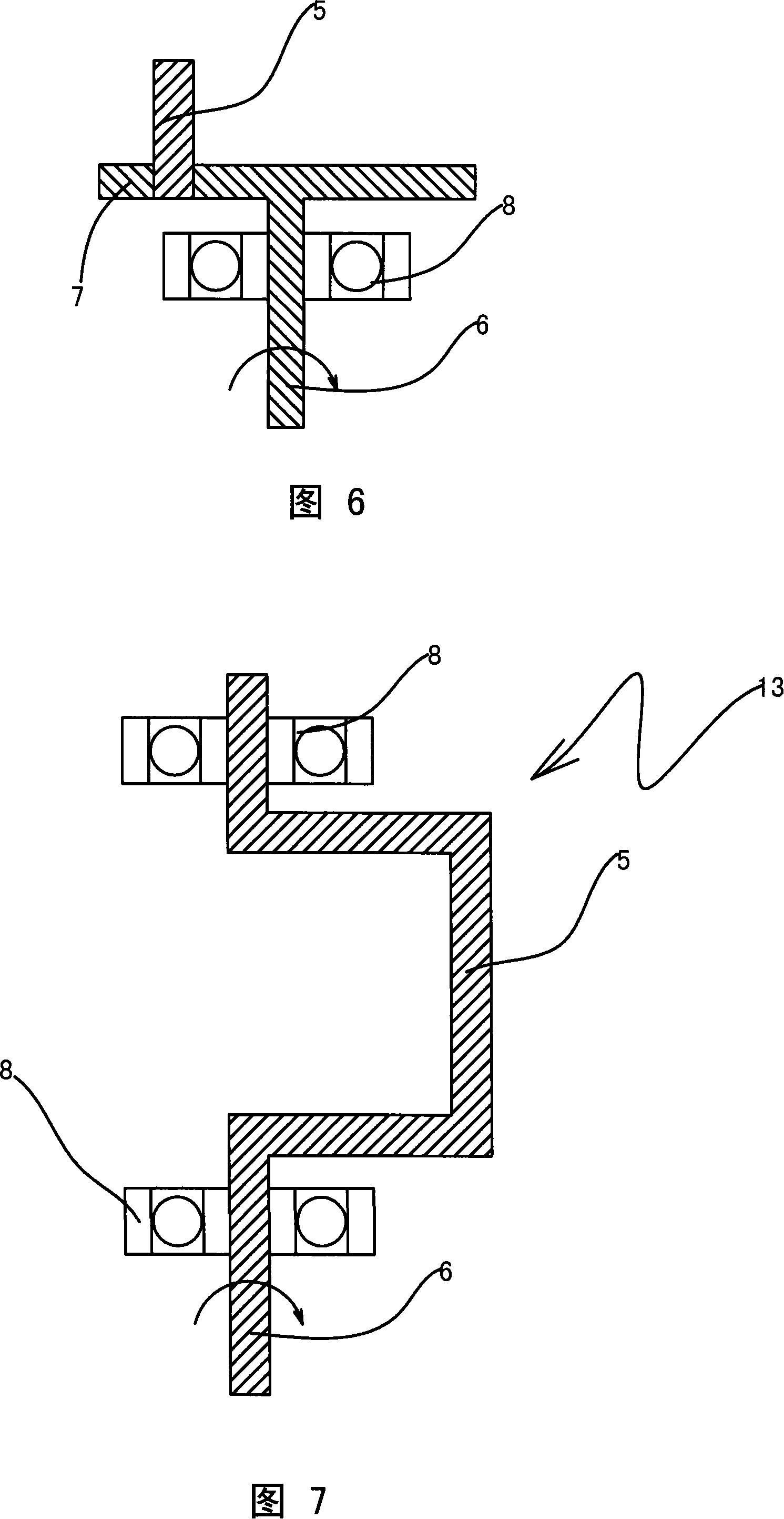
[0036] Referring to accompanying drawings 4, 7, 10 and 11, a grinding and polishing machine includes a housing 12, an eccentric rotation mechanism, a reciprocating linear movement mechanism and a clamp 9, an eccentric rotation mechanism and a reciprocating linear movement mechanism Built in the housing 12; the eccentric rotation mechanism is mainly composed of a crankshaft, one end of the crankshaft is provided with a rotating shaft 6, the rotating shaft 6 is supported in the housing through a bearing 8, and the middle part of the crankshaft is an eccentric shaft 5, due to the rotating shaft 6 and the axes of the eccentric shaft 5 are arranged parallel to each other and at a distance from each other to form an eccentric structure.
[0037] Referring to accompanying drawings 4, 7, 10 and 11, the reciprocating linear motion mechanism includes a main shaft 1, a secondary shaft 2, a slide groove 11, a connecting rod 3, and a swing rod 4; the eccentric rotation mechanism The eccent...
Embodiment 2
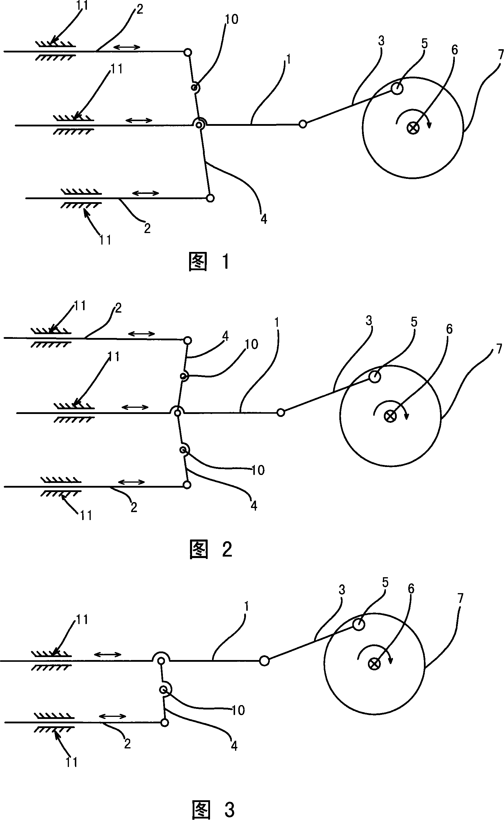
[0039] Referring to accompanying drawing 3, accompanying drawing 5, accompanying drawing 9, accompanying drawing 12 and accompanying drawing 13, a kind of grinding polishing machine comprises housing 12, eccentric rotating mechanism, reciprocating linear moving mechanism and fixture 9, eccentric rotating mechanism and reciprocating linear motion The movement mechanism is set in the housing 12; the eccentric rotation mechanism is mainly composed of an eccentric bearing 14, the outer ring of the eccentric bearing 14 is fixedly connected to the inner ring of the bearing sleeve 15, and the inner ring of the eccentric bearing 14 is fixedly connected to the eccentric shaft 5. The base of the bearing sleeve 15 is provided with a rotating shaft 6, and the rotating shaft 6 is supported in the housing through the bearing 8. (The eccentric mechanism can also be formed by an ordinary bearing. The inner ring is fixedly connected to the eccentric shaft 5, and the base of the bearing sleeve 1...
Embodiment 3
[0042]Referring to accompanying drawing 1, accompanying drawing 6, accompanying drawing 8, accompanying drawing 14 and shown in accompanying drawing 15, a kind of grinding polishing machine comprises housing 12, eccentric rotating mechanism, reciprocating linear motion mechanism and fixture 9, eccentric rotating mechanism and The reciprocating linear motion mechanism is located in the housing 12; the eccentric rotation mechanism is mainly composed of a disc 7, one end of the disc 7 is provided with a rotating shaft 6, and the rotating shaft 6 is supported in the housing by a bearing 8, and the rotating shaft 6 The upper end is affixed to the center of the lower end of the disc 7; the upper end of the disc 7 is positioned at a position different from the center of the disc 7 and the eccentric shaft 5 is positioned; since the axes of the rotating shaft 6 and the eccentric shaft 5 are arranged parallel to each other and apart from each other, the eccentric structure.
[0043] Ref...
PUM
 Abstract
Description
Claims
Application Information
 - R&D
- Intellectual Property
- Life Sciences
- Materials
- Tech Scout
- Unparalleled Data Quality
- Higher Quality Content
- 60% Fewer Hallucinations
Browse by: Latest US Patents, China's latest patents, Technical Efficacy Thesaurus, Application Domain, Technology Topic, Popular Technical Reports.
© 2025 PatSnap. All rights reserved.Legal|Privacy policy|Modern Slavery Act Transparency Statement|Sitemap|About US| Contact US: help@patsnap.com