Edge peeling bearing plate for tentering boarding machine
A stenter setting machine and edge stripping technology, applied in textiles and papermaking, fabric surface trimming, fabric elongation, etc., can solve the problems of cloth waste, edge curling, etc., to avoid waste, avoid edge curling, and improve performance Effect
- Summary
- Abstract
- Description
- Claims
- Application Information
AI Technical Summary
Problems solved by technology
Method used
Image

Examples
Embodiment 1
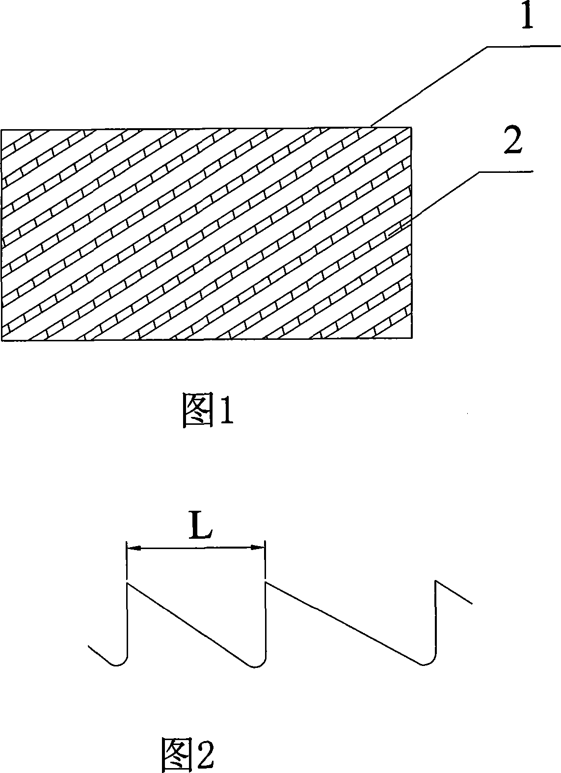
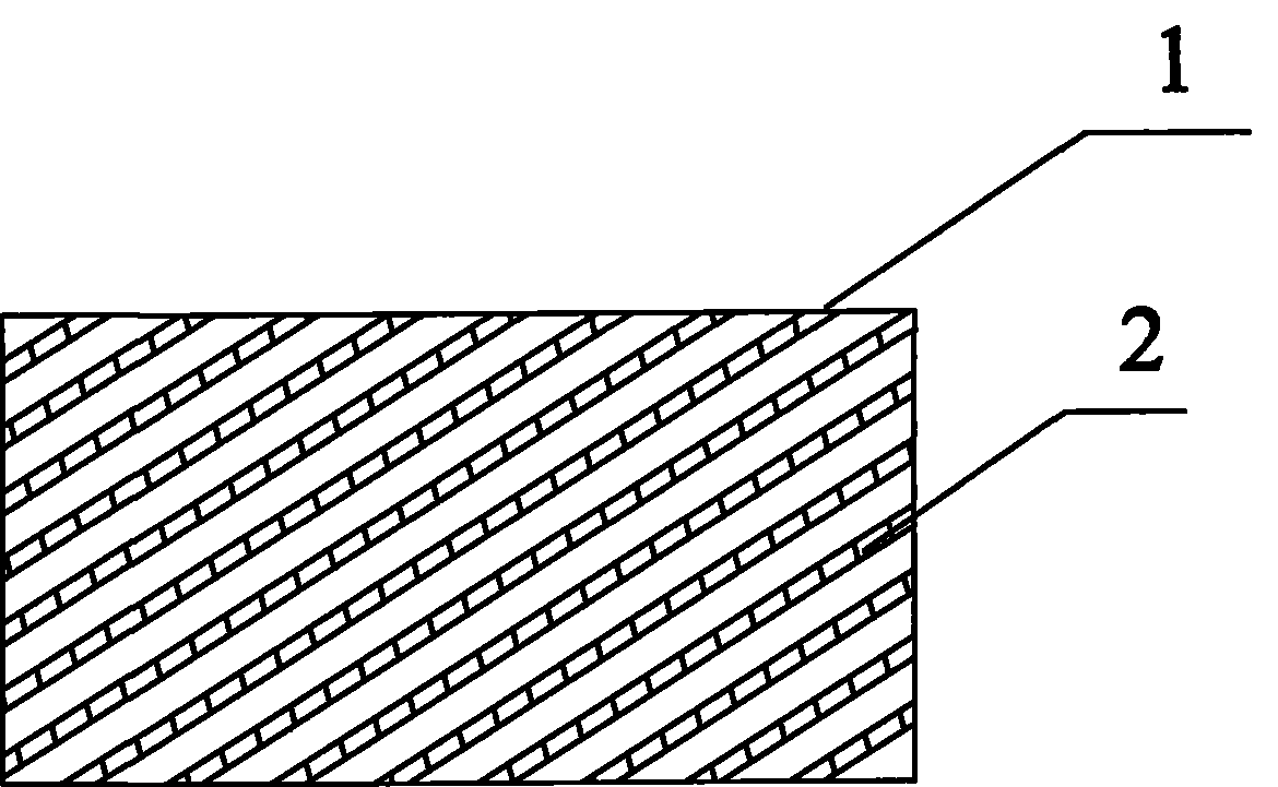
[0013] Example 1 An edge stripping pallet for a tenter setting machine. On the surface of the flat plate 1, there are arranged dentate protrusions 2 arranged obliquely, and the dentate protrusions 2 are arranged at intervals. The tooth lines of the dentate protrusions 2 and the flat plate 1 The included angle between the two adjacent tooth lines is 10-16°, and the distance between two adjacent tooth lines is 3-5 cm. In this embodiment, the above-mentioned included angle is 10°, and the distance between two adjacent tooth lines is 3. Cm, the present invention is used in pairs, placed up and down, and the tooth-like protrusions 2 of the edge stripping pallet located on the upper side are just opposite to the gap between the two adjacent tooth-like protrusions 2 of the edge stripping pallet located below, And it is used on both sides of the guide rail at the same time.
Embodiment 2
[0014] Example 2 A stripping pallet for a tenter setting machine. On the surface of the flat plate 1, there are arranged obliquely arranged tooth-like protrusions 2 and the tooth-like protrusions 2 are arranged at intervals. The tooth lines of the tooth-like protrusions 2 and the flat plate 1 The angle between the two adjacent tooth lines is 10-16°, and the distance between two adjacent tooth lines is 3-5 cm. In this embodiment, the above-mentioned angle is 11°, and the distance between two adjacent tooth lines is 3. Cm, the present invention is used in pairs, placed up and down, and the tooth-like protrusions 2 of the stripping pallet located on the upper side are exactly opposite to the gap between the two adjacent tooth-like protrusions 2 of the bottom stripping pallet, And it is used on both sides of the rail at the same time.
Embodiment 3
[0015] Example 3 An edge stripping pallet for a tenter setting machine. On the surface of the flat plate 1, there are dentate protrusions 2 arranged obliquely, and the dentate protrusions 2 are arranged at intervals. The tooth lines of the dentate protrusions 2 and the flat plate 1 The included angle between the two adjacent tooth lines is 10-16°, the distance between two adjacent tooth lines is 3-5 cm, in this embodiment the above-mentioned included angle is 12 °, and the distance between two adjacent tooth lines is 4 Cm, the present invention is used in pairs, placed up and down, and the tooth-like protrusions 2 of the edge stripping pallet located on the upper side are just opposite to the gap between the two adjacent tooth-like protrusions 2 of the edge stripping pallet located below, And it is used on both sides of the rail at the same time.
PUM
 Abstract
Description
Claims
Application Information
 - R&D
- Intellectual Property
- Life Sciences
- Materials
- Tech Scout
- Unparalleled Data Quality
- Higher Quality Content
- 60% Fewer Hallucinations
Browse by: Latest US Patents, China's latest patents, Technical Efficacy Thesaurus, Application Domain, Technology Topic, Popular Technical Reports.
© 2025 PatSnap. All rights reserved.Legal|Privacy policy|Modern Slavery Act Transparency Statement|Sitemap|About US| Contact US: help@patsnap.com