Floating taper cock valve

A plug valve and cone technology, applied in the field of floating cone plug valve, can solve the problems of complex valve structure, the plug valve has not been widely used, and the operation is inconvenient, and achieves the effect of reliable sealing, good sealing performance and simple structure

Inactive Publication Date: 2008-03-19
虞仕君
View PDF0 Cites 43 Cited by
  • Summary
  • Abstract
  • Description
  • Claims
  • Application Information

AI Technical Summary

Problems solved by technology

However, more than two operating mechanisms or more than two actions are required, which makes the valve structure complex and inconvenient to operate. Therefore, this type of improved plug valve has not been widely used.

Method used


Image

  • Floating taper cock valve
  • Floating taper cock valve
  • Floating taper cock valve

Examples


Embodiment 1

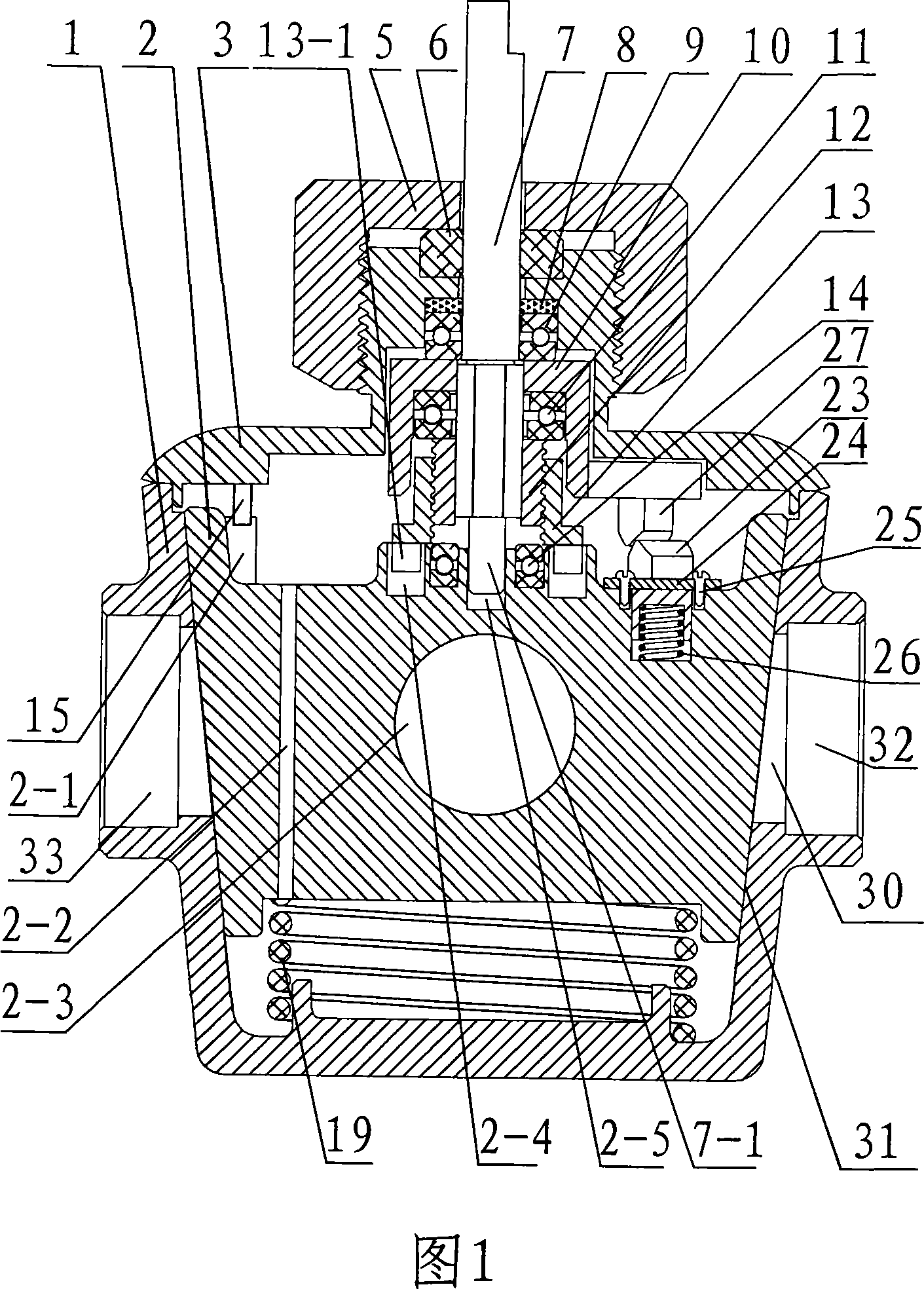
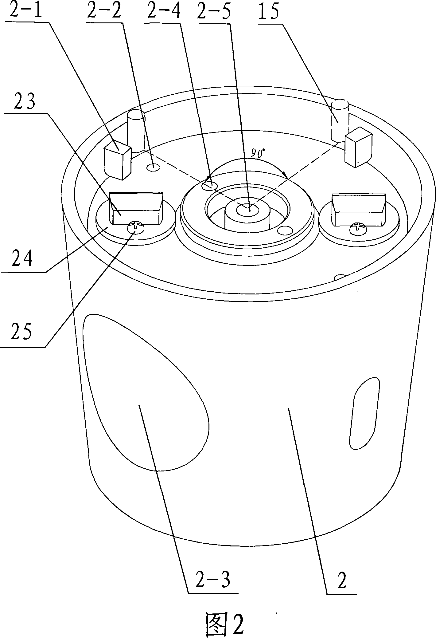
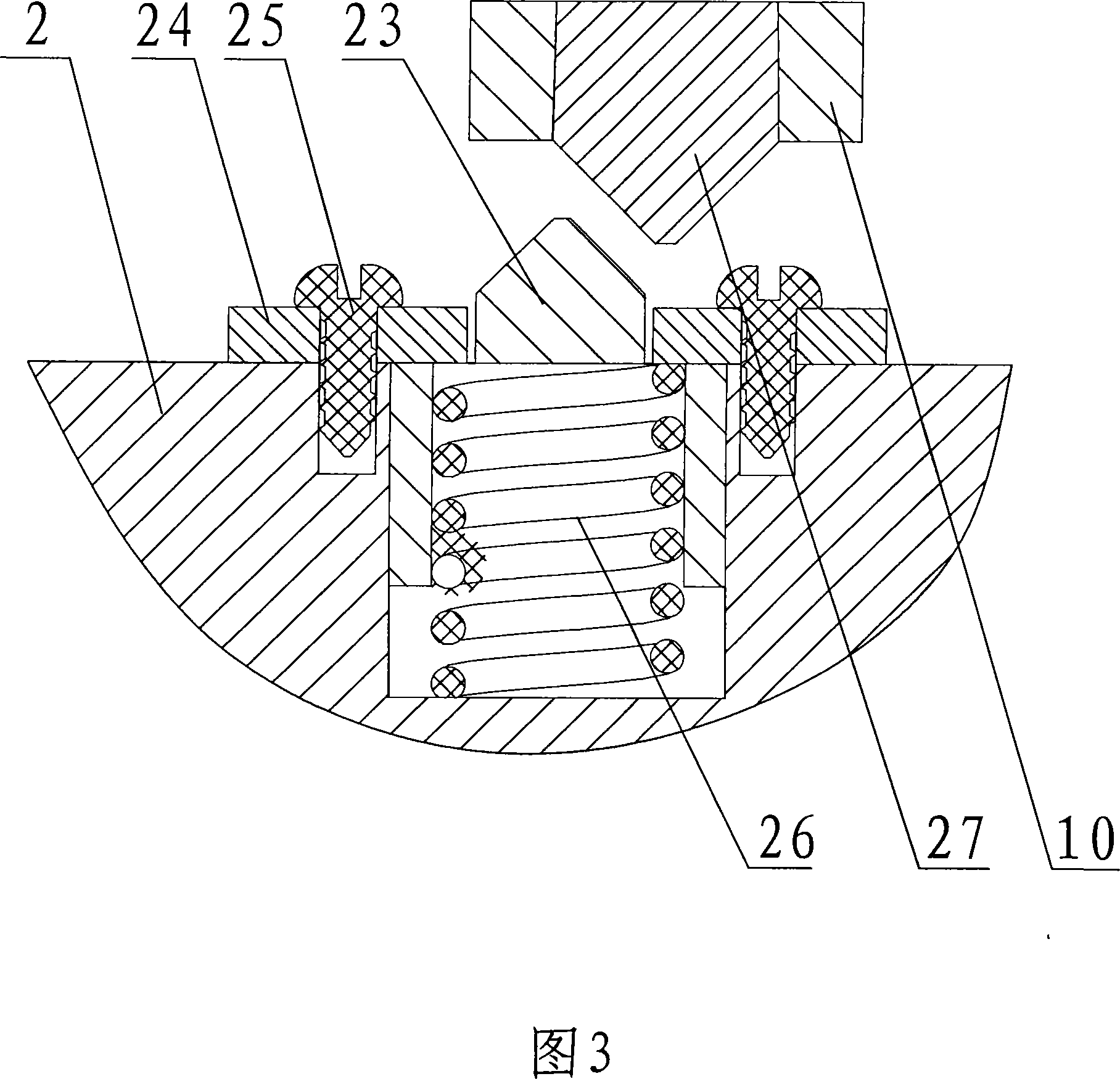
[0034] As shown in Figure 1, it is a structural diagram of a floating conical plug valve. The valve is in a closed state. The floating conical plug valve includes a valve body 1. The valve body 1 has an inlet 32 ​​and an outlet 33. The valve body 1 is provided with a supply valve. A through passage 30 through which the medium flows, and the valve also includes a tapered valve cavity 31 intersecting the passage 30, a rotatably set in the valve cavity 31 for blocking the valve in the closed state of the valve. The conical spool 2 of the passage 30, the spool 2 is a floating conical plug spool that can move up and down in the valve chamber 31, the valve also includes a rotary transmission sleeve 10 and a valve stem for rotating the spool 2 7. The rotating transmission sleeve 10 is set outside the valve stem 7. A floating spring 19 is provided between the lower part of the valve core 2 and the bottom of the valve body 1. The lower end of the valve cover 3 is provided with a limit p...

Embodiment 2

[0047] As shown in Figure 8, it is a structural schematic diagram of a floating conical plug valve provided with a spring pressure plate steel ball in Embodiment 2. The valve is in a closed state, and a steel ball is provided between the bottom center of the valve core 2 and the spring 19 through a spring pressure plate 17. 18, its purpose is to reduce the friction between the spring 19 and the spool 2 when the spool rotates, and the rest are the same as in embodiment 1.

Embodiment 3

[0049] As shown in Figure 9, it is a schematic structural diagram of a four-way floating conical plug valve in Embodiment 3. The difference from Embodiment 1 is that the valve core 2 is provided with two flow channels 2-7 and 2-8, and the valve body 1 is provided with etc. Angle D, E, F, G four ports, the rest are the same as embodiment 1, port D and port E communicate with flow channel 2-7, port F and port G communicate with flow channel 2-8, when spool 2 After rotating 90 degrees counterclockwise, port D and port F communicate with flow channel 2-7, and port E and port G communicate with flow channel 2-8 to achieve the purpose of fluid reversing.


PUM


Abstract

The invention relates to a floating taper cone plug valve. The invention comprises a valve body, a perforated channel for media flowing arranged on the valve body, a tapered valve cavity intersected with the channel, a tapered valve core rotatablely arranged in the valve cavity for shutting off the channel under the off state, a valve rod for rotating the valve core, springs arranged between the bottom part of the valve core and the valve cavity, and a valve cover arranged at the upper end of the valve body. The invention is characterized in that the valve core is a floating taper cone plug valve core being able to move longitudinally in the valve cavity, a rotating driving sleeve with a torsion limiting sliding block and a torsion delivering pin arranged at the upper end of the valve core is arranged at the outer part of the valve rod, the torsion limiting sliding block and the torsion delivering pin form a torsion limitator, a telescopic inner sleeve matched with threads is arranged between the rotating driving sleeve and the valve rod, and a telescopic outer sleeve is arranged at the outer part of the telescopic inner sleeve. The invention can lead the valve core to float to be hoisted-rotate for a certain angle-press down-seal only with a operation mechanism performing ingle directional rotating, lubricant films are not required between the valve cavity and the valve core, thus the invention has no rotating friction and rotating wearing, the wearing is low, the sealability is high, and the structure is simple.

Description

technical field [0001] The present invention relates to a floating conical cock valve, in particular to a floating conical cock valve which can change the direction of the fluid or make it on and off. An electric valve belongs to the technical field of valves. Background technique [0002] Due to the simple structure, fast switching and small pressure drop, the plug valve is widely used in a certain range. [0003] A sealing and lubricating film must be established between the tapered outer surface of the current plug valve and the tapered inner surface of the valve cavity, and the axial seal specific pressure is installed at the large end of the plug, and the plug valve core still retains the same sealing when rotating Specific pressure, so the torque during rotation is large, and the wear of the sealing surface is also large. When subjected to high temperature impact, the vibration will destroy the lubricating film, causing the cock to stick to the valve cavity and cannot...

Claims


Application Information

Patent Timeline
Patent Type & Authority Applications(China)
IPC IPC(8): F16K5/02F16K5/16F16K11/083
CPCF16K5/02F16K11/0833
Inventor 虞仕君
Owner 虞仕君
Why Eureka
Try Eureka