Dc-dc convertir system

A DC converter and state technology, applied in the direction of converting DC power input to DC power output, high-efficiency power electronic conversion, output power conversion device, etc. Effect

Inactive Publication Date: 2008-03-19
DENSO CORP +1
View PDF1 Cites 8 Cited by
  • Summary
  • Abstract
  • Description
  • Claims
  • Application Information

AI Technical Summary

Problems solved by technology

[0009] However, even in the current limiting type DC-DC converter system, when the power demand from the load system is large, the output current of the DC-DC converter must be kept at the limit value within the overheating temperature state (lines 101, 102, 103 )
As a result, overheat suppression cannot be obtained to a satisfactory degree

Method used


Image

  • Dc-dc convertir system
  • Dc-dc convertir system
  • Dc-dc convertir system

Examples


Embodiment Construction

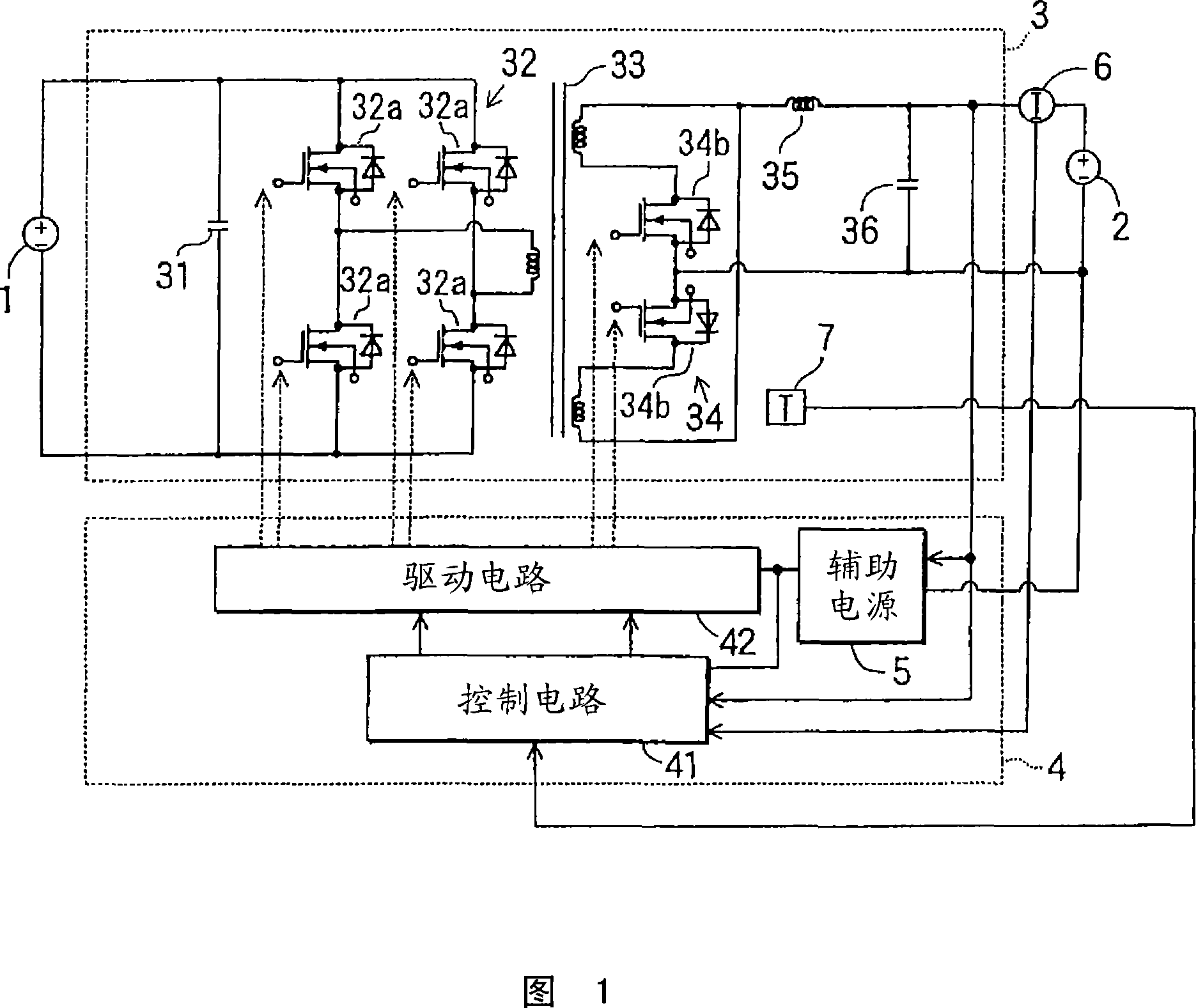
[0026] In the preferred embodiment shown in FIG. 1, the DC-DC converter system is applied to a dual-battery type vehicle power supply system.

[0027] This dual battery type vehicle power supply system is connected to a main battery 1 and an auxiliary battery 2, and has a battery charging DC-DC converter 3, a DC-DC converter for controlling the switching operation of this battery charging DC-DC converter 3 Control circuit unit 4. This power system is configured to supply power from the main battery 1 to an electronic controller (not shown) for use in charging the hybrid vehicle with traction energy after converting its voltage, and to supply power to auxiliary or accessory equipment and the auxiliary battery 2 for auxiliary purposes. The power system is also connected to the current sensor 6 and the temperature sensor 7 .

[0028] The DC-DC converter 3 for battery charging employs a well-known circuit configuration including an input smoothing capacitor 31, a full-bridge inv...


PUM


Abstract

A DC-DC converter system is provided to improve switching control operation of a battery charging DC-DC converter (3) in an overheat temperature state without necessitating complication of a control unit (4). The control unit (4) performs output voltage limitation as well as output current limitation when the temperature of the DC-DC converter (3) is in an overheat temperature state in the vicinity of its operation stop temperature. With this capability, the output current and the output voltage can be limited, and therefore overheating of a power switching device (32) of the DC-DC converter (3) can be inhibited. In an alternative embodiment the switching frequency of the power switching device (32) is limited.

Description

technical field [0001] The present invention relates to a DC-DC converter system that supplies an output from a DC power source to an electrical load system through conversion by a switch built-in power switching device. [0002] This application is based on Japanese Patent Application No. 2005-87004 filed on March 24, 2005 and is incorporated by reference. Background technique [0003] For vehicle power systems for hybrid vehicles and idle-stop vehicles, a dual-battery type vehicle power system is proposed. In this unit, two batteries with different supply voltages are used for the vehicle power system. Further, high voltage batteries of tens or hundreds of volts supply power to large electrical loads, while low voltage batteries exceeding ten volts, such as lead batteries, supply power to low electrical loads. The high voltage battery is charged by a high voltage power generation device. A low-voltage battery or a low-voltage load connected to it is powered by a high-vo...

Claims


Application Information

Patent Timeline
Patent Type & Authority Applications(China)
IPC IPC(8): H02M1/00H02J7/00
CPCH02M1/32Y02B70/1475H02J7/047H02M3/33592H02J7/007192Y02B70/10H02J7/04Y02B40/00
Inventor 山下刚大塚健司户田守
Owner DENSO CORP
Why Eureka
Try Eureka