Method for mounting seabed anchor

An installation method and technology of anchor barrels, which are applied in the direction of anchor points, transportation and packaging, ship parts, etc., can solve the problems of small insertion depth, loss of anchoring effect, etc.

Inactive Publication Date: 2008-03-26
INST OF MECHANICS - CHINESE ACAD OF SCI
View PDF0 Cites 7 Cited by
  • Summary
  • Abstract
  • Description
  • Claims
  • Application Information

AI Technical Summary

Problems solved by technology

Since this installation method is realized by using the pressure difference inside and outside the anchor barrel, once it is filled with seabed soil, the pressure difference will not be formed, and the anchor barrel can

Method used


Image

  • Method for mounting seabed anchor

Examples


Embodiment Construction

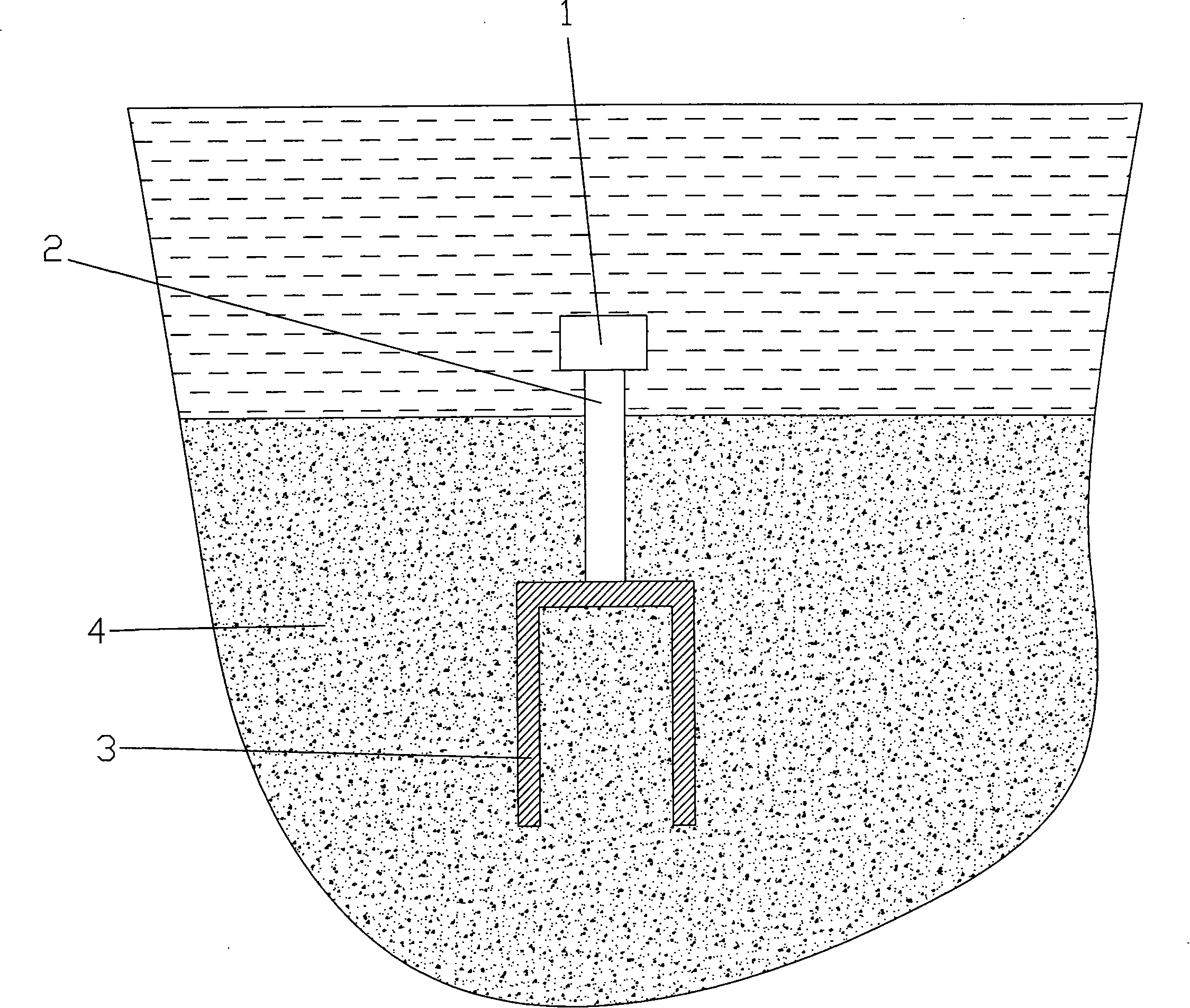
[0010] As shown in the drawings, according to the method of the present invention, when carrying out the anchoring operation of the seabed anchor, at first the mechanical vibration device 1 is installed on the top of the anchor tube 3 through the strut 2, and the length of the strut 2 and the top of the anchor tube 3 are submerged in the seabed soil. Then, the anchor cylinder 3 is automatically inserted into the seabed soil 4 by using the mechanical vibration generated by the mechanical vibration device and the self-weight of the anchor cylinder.

[0011] During the insertion process of the anchor tube 3 into the soil body 4, the soil around the anchor tube 3 will continue to soften and even liquefy with the vibration, and the anchor tube 3 will continuously discharge the softened soil around it to the outside under the action of its own weight , and gradually penetrate deep into the soil.

[0012] Since the present invention utilizes the feature that the soil body will soften...


PUM


Abstract

The seabed anchor pipe installing process includes setting one mechanical vibrating unit in the top of anchor pipe, setting the anchor pipe on the seabed earth body, and inserting the anchor pipe to required depth for anchoring by means of mechanical vibration and the dead weight of the anchor pipe. Applying mechanical vibration can soften or even liquefy the earth body around the anchor pipe to reduce the resistance to the inserted anchor pipe. The present invention can ensure sufficient anchoring effect.

Description

technical field [0001] The invention relates to a method for installing an anchor in the seabed soil on the seabed. Background technique [0002] In order to maintain the stability of marine facilities such as offshore platforms, it is usually necessary to set anchors on the seabed and use anchors to fix marine facilities. Restricted by the construction environment, most of the existing seabed anchors are driven in by direct pressing or hammering. These two installation methods are costly and long-term. Recently, there is a new method, that is, it is prefabricated into a cylindrical shape with one end open and one end closed. At the construction site, the water or air in the anchor barrel is pumped to form a negative pressure in the anchor barrel, and the pressure generated inside and outside the anchor barrel is used. Poor, the anchor tube is pressed into and anchored in the seabed soil. Since this installation method is realized by using the pressure difference inside an...

Claims


Application Information

Patent Timeline
IPC IPC(8): B63B21/26
Inventor 赵京王爱兰王淑云鲁晓兵
Owner INST OF MECHANICS - CHINESE ACAD OF SCI
Why Eureka
Try Eureka