Method for detecting lens module performance

A lens module and lens detection technology, which is applied in optics, instruments, photography, etc., can solve problems such as no image, damage to the light range of the outgoing lens module, and out-of-range light range of the incident lens module, so as to achieve small space and avoid Assembling defective products and reducing production costs

Inactive Publication Date: 2010-05-12
HONG FU JIN PRECISION IND (SHENZHEN) CO LTD +1
View PDF2 Cites 2 Cited by
  • Summary
  • Abstract
  • Description
  • Claims
  • Application Information

AI Technical Summary

Problems solved by technology

[0004] However, after the lens module is assembled, if the center of the entrance pupil or the exit pupil of the lens module is not located on the central axis of the lens barrel, the light range of the incident lens module may not be the expected range, or the output The light range of the lens module is damaged. In this case, the image formed on the photosensitive element will not be ideal as expected

Method used


Image

  • Method for detecting lens module performance
  • Method for detecting lens module performance
  • Method for detecting lens module performance

Examples


Embodiment Construction

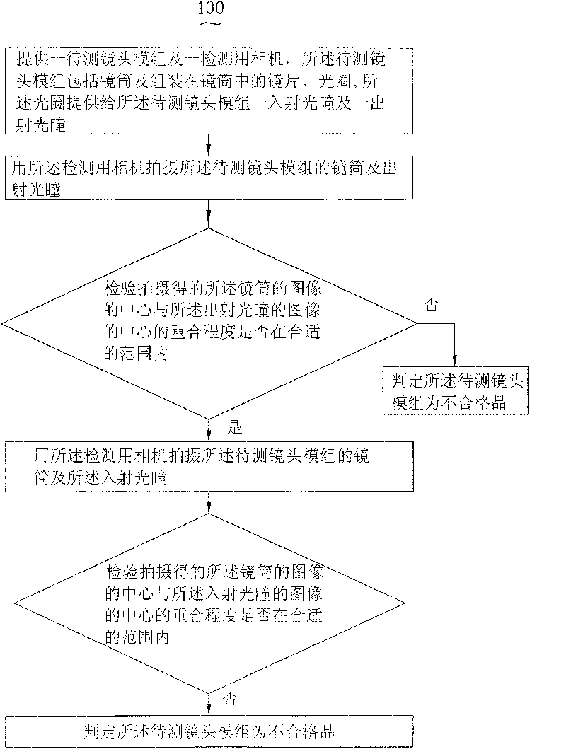
[0023] The method for detecting the performance of the lens module provided by the present invention will be further described in detail below in conjunction with the accompanying drawings.

[0024] Please also refer to Figure 1 to Figure 3 The method 100 for detecting the performance of the lens module provided by the first embodiment of the present invention includes the following steps:

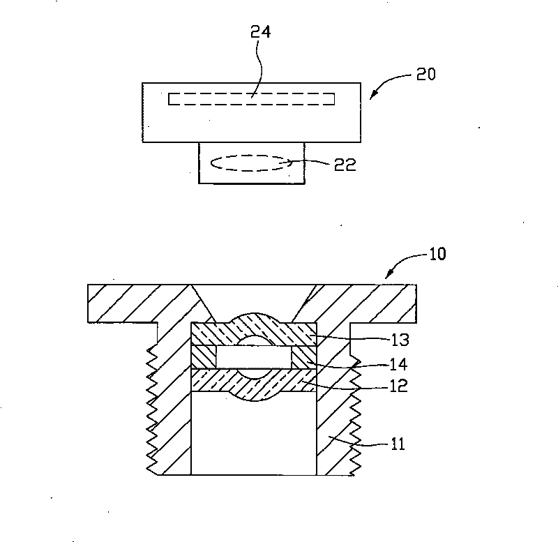
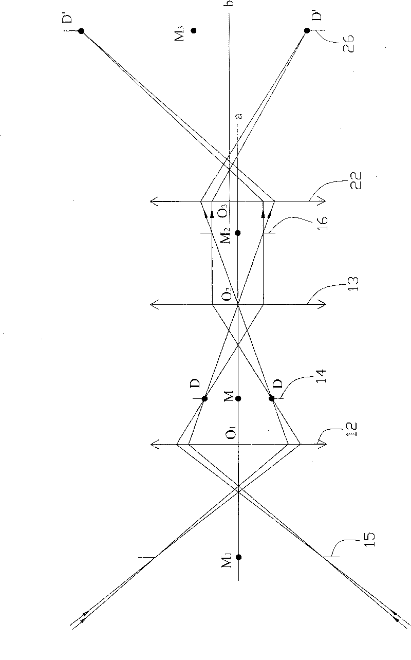
[0025] (1) Provide a lens module 10 to be tested and a camera 20 for detection, the lens module 10 to be tested includes a lens barrel 11, two lenses assembled in the lens barrel 11 in sequence from the object side to the image side 12, 13, and an aperture 14 sandwiched between the eyeglasses 12, 13, the aperture 14 forms an entrance pupil 15 on the object side of the lens module 10 to be tested through the eyeglass 12, through The lens 13 forms an exit pupil 16 on the image side of the lens module 10 to be tested;

[0026] (2) photographing the lens barrel 11 and the exit pupil 16 of t...


PUM


Abstract

This invention relates to a sort of method which is used for checking the capability of the lens module, and it includes these approaches in that: offer a future measuring lens module and a checking camera, and this checking lens module consists of the drawtube, the lens which is fixed in the drawtube, and the aperture, and this aperture offers a entrance pupil and a emergent pupil to this futuremeasuring lens module. Shoot this drawtube of this future measuring lens module and the emergent pupil by this checking camera. Check that if the superposition degree of this picture center of this drawtube and the picture center of this emergent pupil is in the equal range, if yes, shoot the drawtube of this future measuring lens module by this checking camera and the entrance pupil again, and then check that if the superposition degree of this picture center of this drawtube and the picture center of this entrancet pupil is in the equal range.

Description

technical field [0001] The invention relates to the field of performance detection of lens modules, in particular to a method for detecting the performance of lens modules. Background technique [0002] With the development of camera functions, camera modules are widely used in camera devices for various purposes. The combination of camera modules and portable electronic devices, such as mobile phones and computers, is favored by many consumers. [0003] A camera module usually includes at least a lens module and a photosensitive element. The lens module may include a lens barrel, and a plurality of lenses (lenses), apertures, filters and the like arranged in the lens barrel. Apertures, filters, etc. can be placed between multiple lenses, on the object side of all lenses, or on the image side of all lenses. The aperture passes through itself, or through the image on the object side of the lens module formed by the lens arranged on the object side (at this time, the apertur...

Claims


Application Information

Patent Timeline
Patent Type & Authority Patents(China)
IPC IPC(8): G03B43/00
Inventor 袁崐益
Owner HONG FU JIN PRECISION IND (SHENZHEN) CO LTD
Why Eureka
Try Eureka