Infra red touch screen and multiple point touching positioning method

A multi-touch, infrared technology, applied in the direction of instrument, electrical digital data processing, data processing input/output process, etc., can solve the problem of increasing cost, touching the location is not the actual touch location, multi-touch can not be recognized, etc. question

Inactive Publication Date: 2008-03-26
GUANGDONG VTRON TECH CO LTD
View PDF3 Cites 72 Cited by
  • Summary
  • Abstract
  • Description
  • Claims
  • Application Information

AI Technical Summary

Problems solved by technology

This grid structure detection method makes the existing infrared touch screen only receive a unique set of position coordinate data within a given period of time. Therefore, when there is only one touch point, the touch screen can work normally. For two or more When the touch points are operated at the same time, the system will calculate the wrong position coordinates, resulting in the reported touch location is not the actual touch location
[0003] Due to the above reasons, the existing infrared touch screen technology will fail in some occasions that need to use multi-touch, such as multiple people playing games at the same time, multiple people writing and drawing at the same time, etc., which greatly limits the application field of infrared touch screen
[0004] With the development of science and technology, the innovation and development of infrared touch screen technology is also going on. In order to solve the problem that multi-touch cannot be recognized, the industry has made many beneficial attempts, such as designing complex auxiliary judgment circuits to enhance the infrared touch screen. The ability to judge multiple touch points, attaching one or two additional cameras to the outer edge of the infrared touch screen to distinguish multiple touch points, etc., all these require changing the structure and system composition of the existing infrared touch screen. Add more cost on the basis of infrared touch screen
At present, there is also a method to identify multiple touch points by detecting the sequence of touch events without changing the hardware. However, when there is no relative movement between multiple touch points, and there is no shape and size value of the touch point to refer to, it is easy to occur. Misjudgment

Method used


Image

  • Infra red touch screen and multiple point touching positioning method
  • Infra red touch screen and multiple point touching positioning method
  • Infra red touch screen and multiple point touching positioning method

Examples


Embodiment

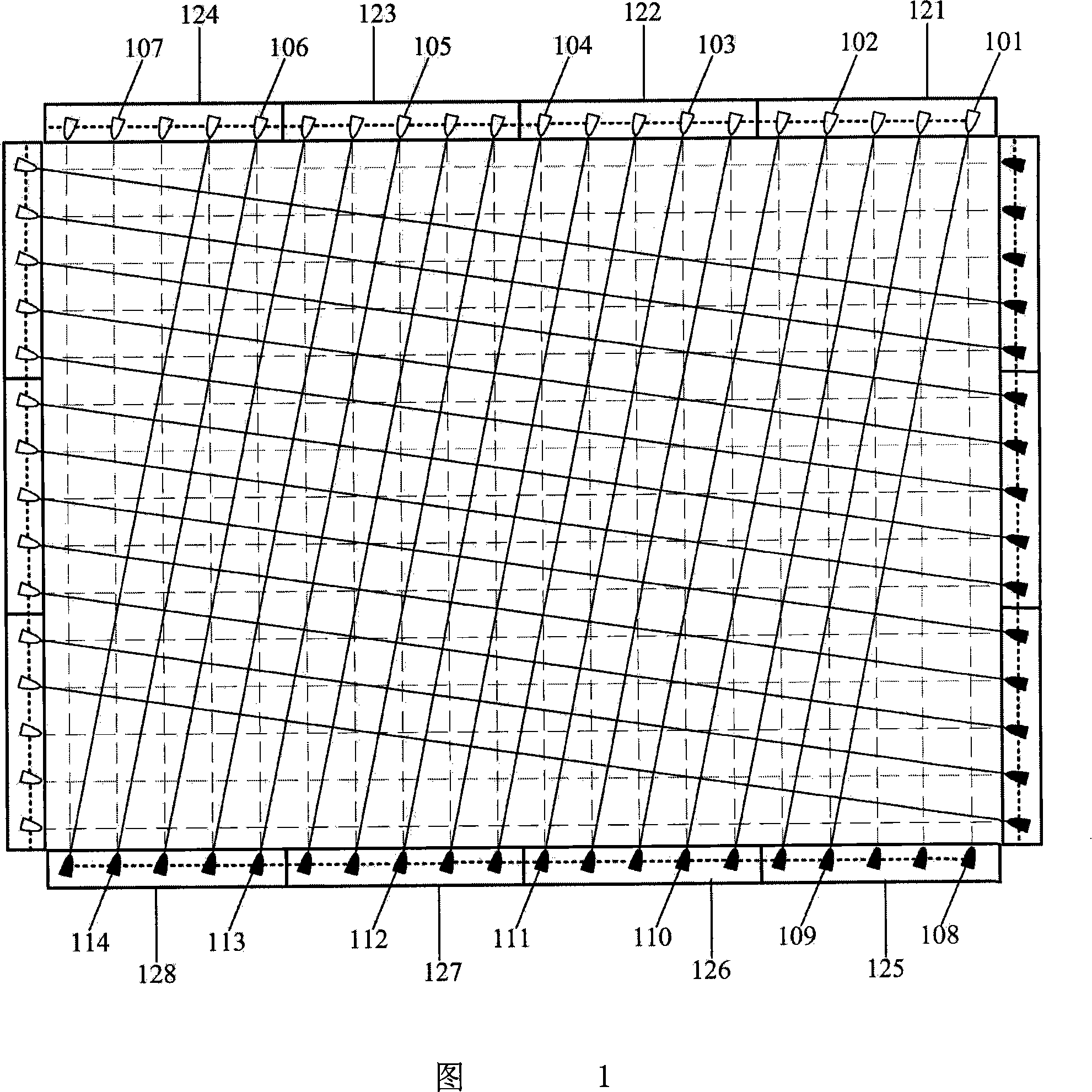
[0055]Fig. 1 is a schematic diagram of the circuit structure of a specific embodiment of the present invention. In the figure, 121, 122, 123, 124 are emitting circuit boards equipped with infrared emitting elements, and 101, 102, 103, 104, 105, 106, 107 are infrared emitting elements installed on the above circuit boards. 108, 109, 110, 111, 112, 113, 114 are infrared receiving elements mounted on receiving circuit boards 125, 126, 127, 128. It can be seen from the figure that the corresponding relationship between the infrared emitting element and the infrared receiving element is different from that of the ordinary infrared touch screen. 109, since the position of 109 deviates from 108 by a certain distance, to simplify the description, the corresponding relationship between 101 and 109 is referred to as oblique relative, and similarly, 102 is obliquely opposite to 110 in addition to being perpendicular to 109; 103 is obliquely opposite to 109 110 is perpendicular to 111, 1...


PUM


Abstract

This invention discloses an infrared touching screen and the multi-spot touching localization method, in an examination direction, the ray of light send out by the infrared emission part on the infrared emission sweep circuit not only can be received at least by one infrared sweep circuit's infrared receive part which is vertical to the part's position, but may also be received by another inclined relative infrared receive sweep circuit's infrared receive part at least which is deviated vertical to the part's position. Thus, in a scanning period, the ray of light send out by an infrared emission part may be received by two different position infrared receive parts in the different time, through a checking calculation between touching possible coordinate figure and location parameter, then may determine each touching position data, this invention realizes the multi-spot localization scanning examination method to be simple, the touching position data computation convenient, accurate, reliable, the circuit wafer type is few, the shape is rule, easy to realize the large scale production, does not have the complex succession corresponding relationships, easy to realize.

Description

technical field [0001] The invention relates to an infrared touch screen, in particular to an infrared touch screen capable of distinguishing multiple touch points for simultaneous operation and a multi-touch positioning method. Background technique [0002] The basic structure of the infrared touch screen currently on the market is to install several pairs of infrared emitting and infrared receiving elements in a certain order on the periphery of a display surface suitable for installation. These transmitting and infrared receiving elements form a transmitting and receiving pair in a one-to-one correspondence, forming a mutually perpendicular transmitting and receiving array along the edge of the display surface, and each pair of transmitting and receiving elements is connected in a certain order under the control of the microcomputer system. and an infrared receiving element to detect whether the infrared light between each pair of infrared emitting and infrared receiving ...

Claims


Application Information

Patent Timeline
Patent Type & Authority Applications(China)
IPC IPC(8): G06F3/042
CPCG06F3/0421G06F2203/04808G06F3/04883
Inventor 卢如西李军明周春景
Owner GUANGDONG VTRON TECH CO LTD
Why Eureka
Try Eureka