Video quality estimating device, method, and program

A quality assessment and video technology, applied in the field of video quality assessment technology, can solve problems such as degradation and easy perception of quality

Active Publication Date: 2008-03-26
NIPPON TELEGRAPH & TELEPHONE CORP
View PDF0 Cites 12 Cited by
  • Summary
  • Abstract
  • Description
  • Claims
  • Application Information

AI Technical Summary

Problems solved by technology

[0005] In audio-visual communication services that transmit

Method used


Image

  • Video quality estimating device, method, and program
  • Video quality estimating device, method, and program
  • Video quality estimating device, method, and program

Examples


no. 1 example

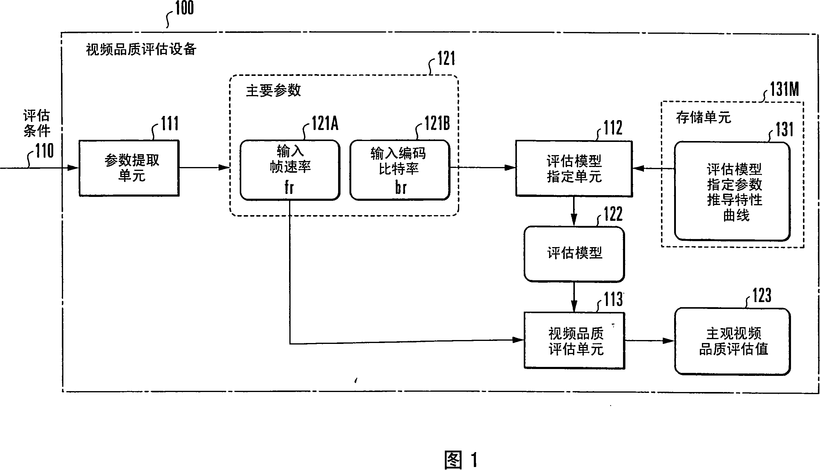
[0061] First, a video quality evaluation device according to a first embodiment of the present invention will be described with reference to FIG. 1 . FIG. 1 is a block diagram showing the arrangement of a video quality evaluation device according to a first embodiment of the present invention.

[0062] The video quality evaluation device 100 is constituted by an information processing device such as a computer that calculates input information. In audio-visual communication for transmitting audio-visual media encoded into a plurality of frames to an arbitrary terminal via a communication network, the video quality evaluation device 100 inputs evaluation conditions related to the audio-visual media, and by using a predetermined evaluation model, calculates the The evaluation value of the subjective video quality actually perceived by the audiovisual media on the Internet.

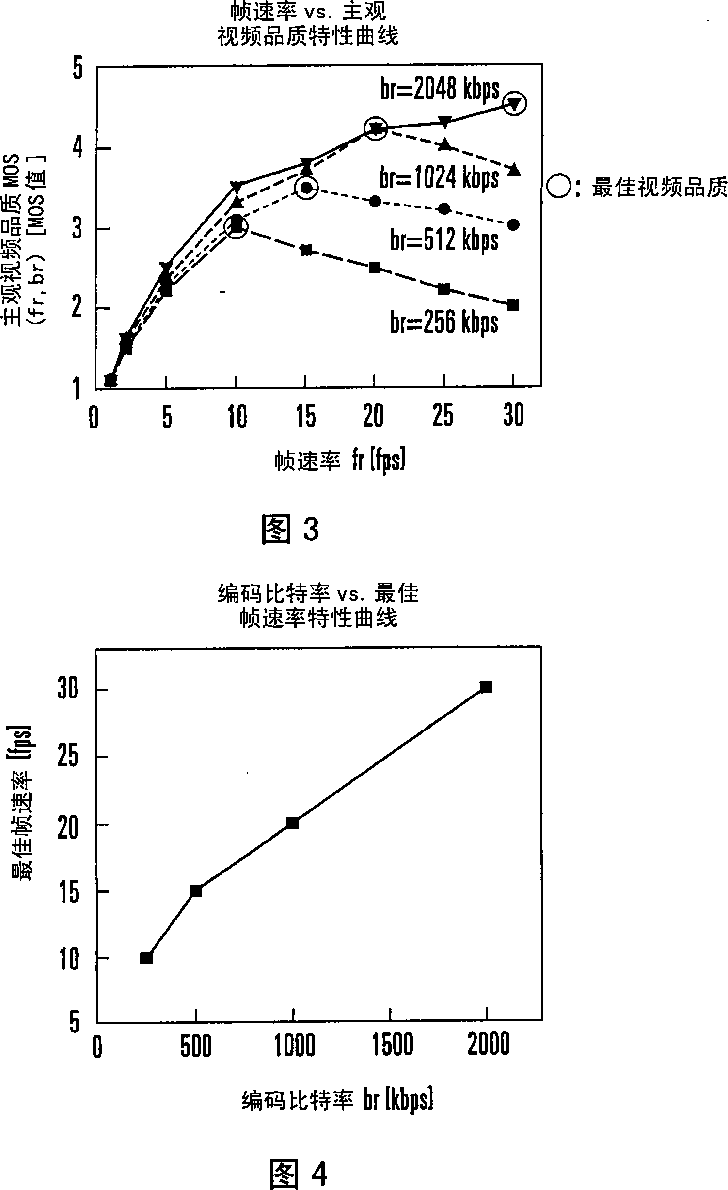
[0063] In this embodiment, subjective parameters corresponding to the main parameters input as the input...

no. 2 example

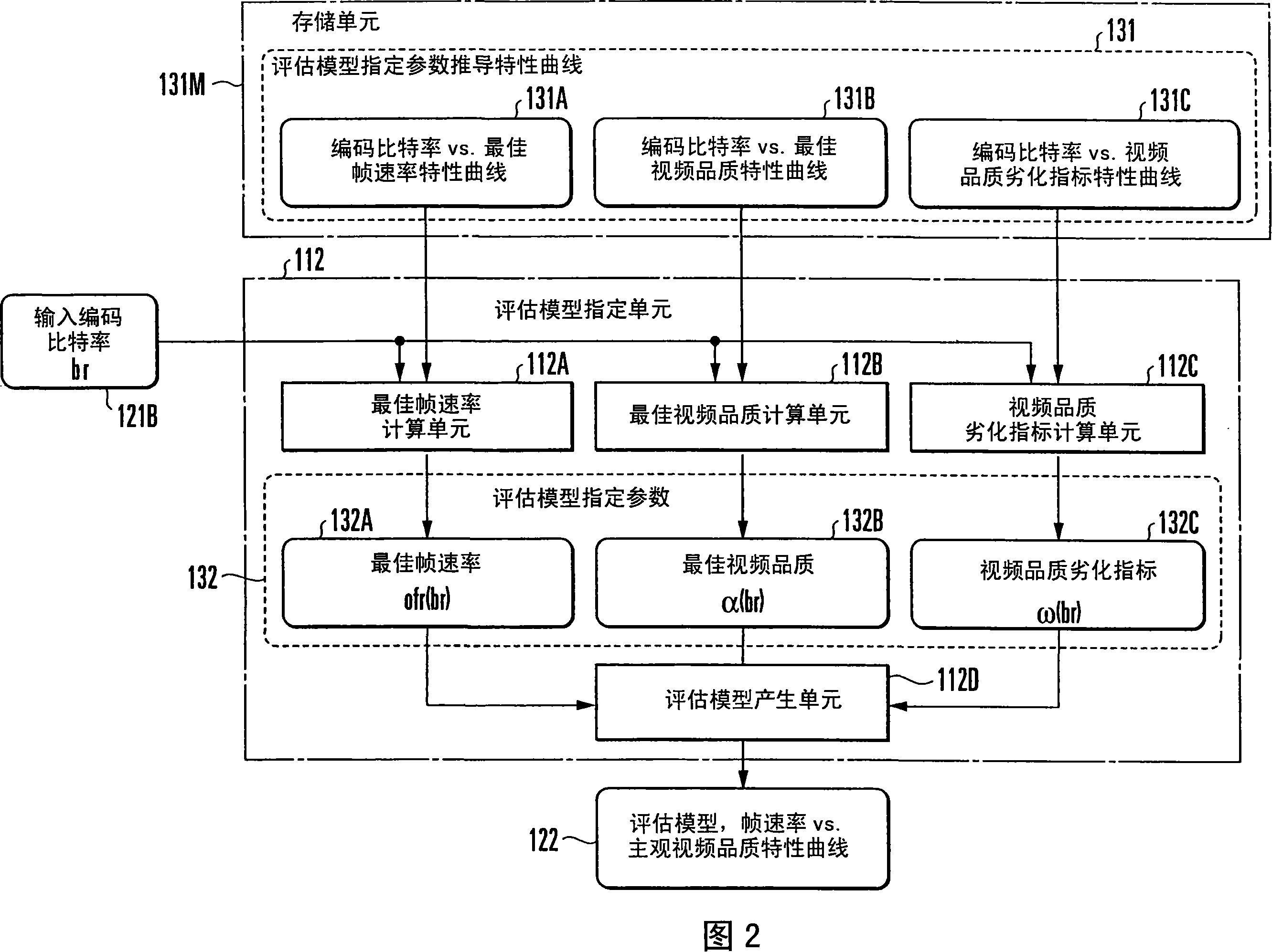
[0126] Next, a video quality evaluation device according to a second embodiment of the present invention will be described with reference to FIGS. 11 and 12 . Fig. 11 is a block diagram showing the arrangement of a video quality evaluation device according to a second embodiment of the present invention. In FIG. 11, the same or similar components are denoted by the same reference numerals as in FIG. 1 described above. 12 is a block diagram showing the arrangement of an evaluation model specifying unit of a video quality evaluation device according to a second embodiment of the present invention. In FIG. 12, the same reference numerals as in FIG. 2 described above are used to designate the same or similar components.

[0127] The first embodiment takes as an example the case where the evaluation model designation parameter 132 corresponding to the input encoding bit rate is derived by referring to the evaluation model designation parameter derivation characteristic curve 131 p...

no. 3 example

[0169] First, a video quality evaluation device according to a third embodiment of the present invention will be described with reference to FIG. 19 . Fig. 19 is a block diagram showing the arrangement of a video quality evaluation device according to a third embodiment of the present invention.

[0170] The video quality evaluation device 200 is formed of an information processing device such as a computer that calculates input information. In audio-visual communication for transmitting audio-visual media encoded into a plurality of frames to an arbitrary terminal via a communication network, the video quality evaluation device 200 inputs evaluation conditions related to the audio-visual media, and calculates the viewer from reproduction at the terminal by using a predetermined evaluation model. The evaluation value of the subjective video quality actually perceived by the audiovisual media on the Internet.

[0171] In this embodiment, in evaluating the main parameters corre...


PUM


Abstract

In estimating subjective video quality corresponding to main parameters (121/221) which are input as an input coding bit rate (121B/221B) representing the number of coding bit rates per unit time and an input frame rate (121A/221A) representing the number of frames per unit time of an audiovisual medium, an estimation model specifying unit specifies, on the basis of the input coding bit rate (121B/input frame rate (221A)), an estimation model (122/222) representing the relationship between subjective video quality and the frame rate (/coding bit rate) of the audiovisual medium. Subjective video quality corresponding to the input frame rate (121A/input coding bit rate 221B) is estimated by using the specified estimation model (122/222) and output as an estimation value (123/223).

Description

technical field [0001] The present invention relates to an audio-visual communication technology, and more particularly, to a video quality evaluation technology for evaluating the subjective video quality actually felt by a viewer when a terminal receives and reproduces audio-visual media encoded into multiple frames. Background technique [0002] Advances in high-speed broadband Internet access technologies have created expectations for audiovisual communication services that transmit audiovisual media including video and audio data between terminals or server terminals via the Internet. [0003] This audio-visual communication service improves audio-visual media transmission efficiency using encoded communication in which audio-visual media is encoded into multiple frames and transmitted using inter-image or intra-image autocorrelation of audio-visual media or human visual characteristics. [0004] On the other hand, best-effort networks such as the Internet for audio-vis...

Claims


Application Information

Patent Timeline
IPC IPC(8): H04N7/26H04N7/173H04N17/04H04N17/00H04N19/00H04N19/115H04N19/132H04N19/134H04N19/162H04N19/196
CPCH04N19/00781H04N7/50H04N7/468H04L43/0894H04N19/00169H04N19/002H04N17/004H04N7/26202H04N19/00206H04N7/26159H04N19/00236H04N7/26196H04N19/00751H04N19/00127H04N7/26228H04L43/08H04N19/61H04N19/132H04N19/146H04N19/154H04N19/156H04N19/164H04N19/587H04N17/00
Inventor 山岸和久林孝典
Owner NIPPON TELEGRAPH & TELEPHONE CORP
Why Eureka
Try Eureka