Sheet conveying device

A technology for conveying devices and sheets, applied in the directions of printing devices, transportation and packaging, printing, etc., can solve the problems of slow belts and reduced printing speed.

Active Publication Date: 2008-04-02
BROTHER KOGYO KK
View PDF1 Cites 18 Cited by
  • Summary
  • Abstract
  • Description
  • Claims
  • Application Information

AI Technical Summary

Problems solved by technology

Due to the increased diameter of these rollers, the belt may start moving more slowly, which ultimately results in a slower print speed

Method used


Image

  • Sheet conveying device
  • Sheet conveying device
  • Sheet conveying device

Examples


Embodiment Construction

[0021] Embodiments are described in detail with reference to the accompanying drawings. One or more embodiments may be applied to an inkjet printer that forms characters and / or images by ejecting ink onto a recording sheet.

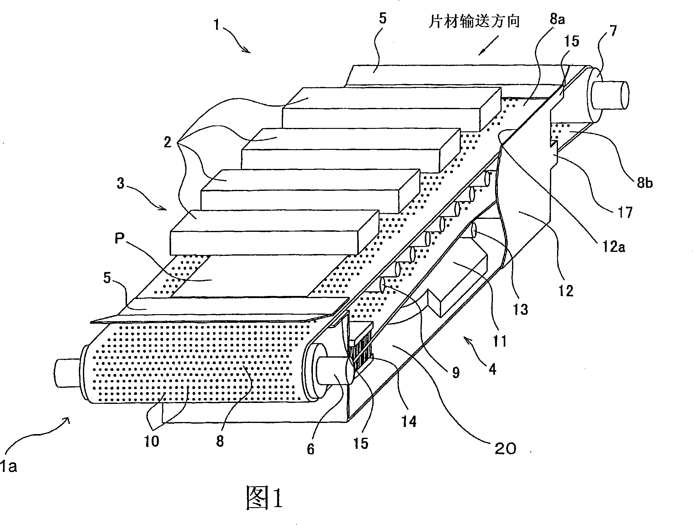
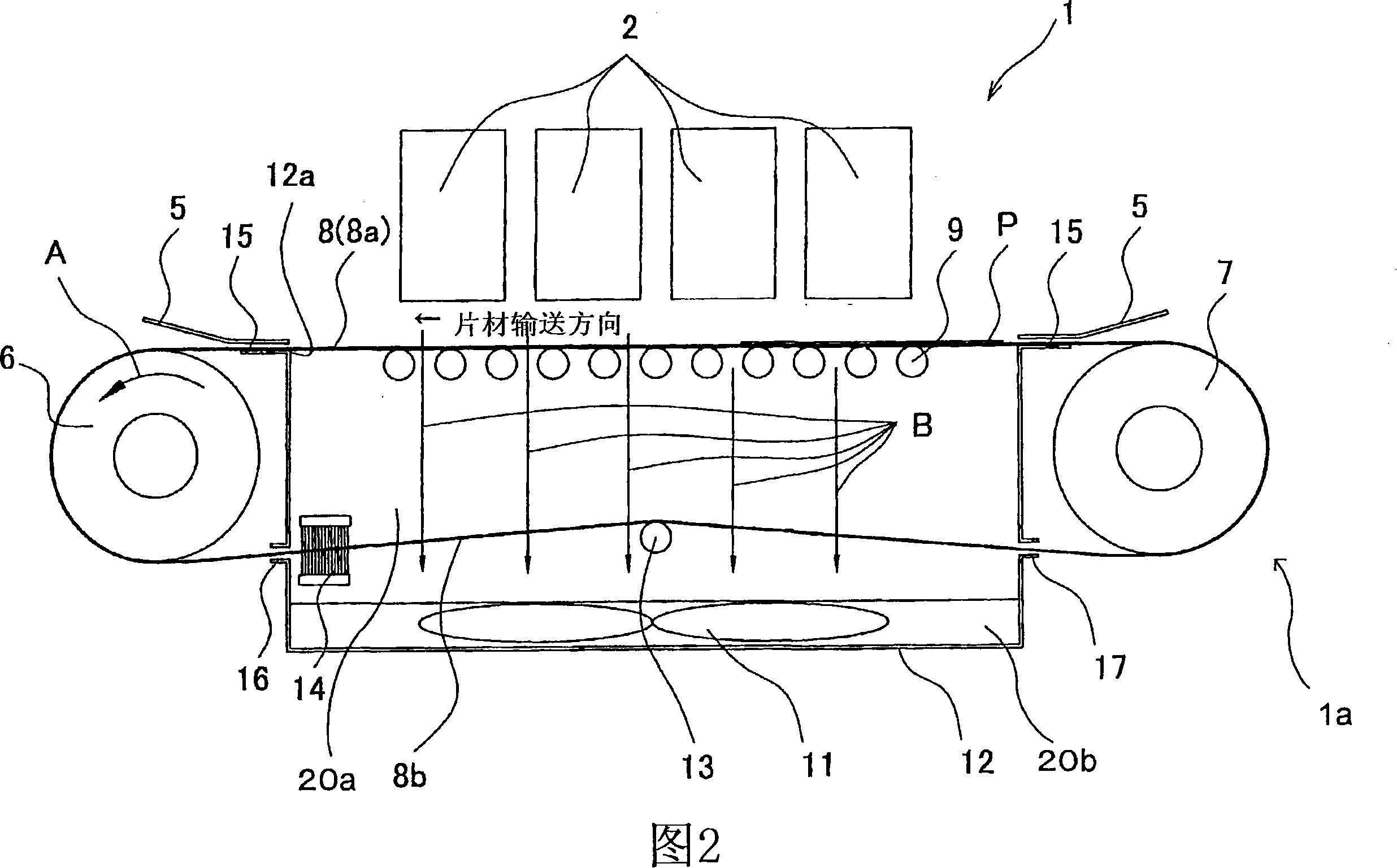
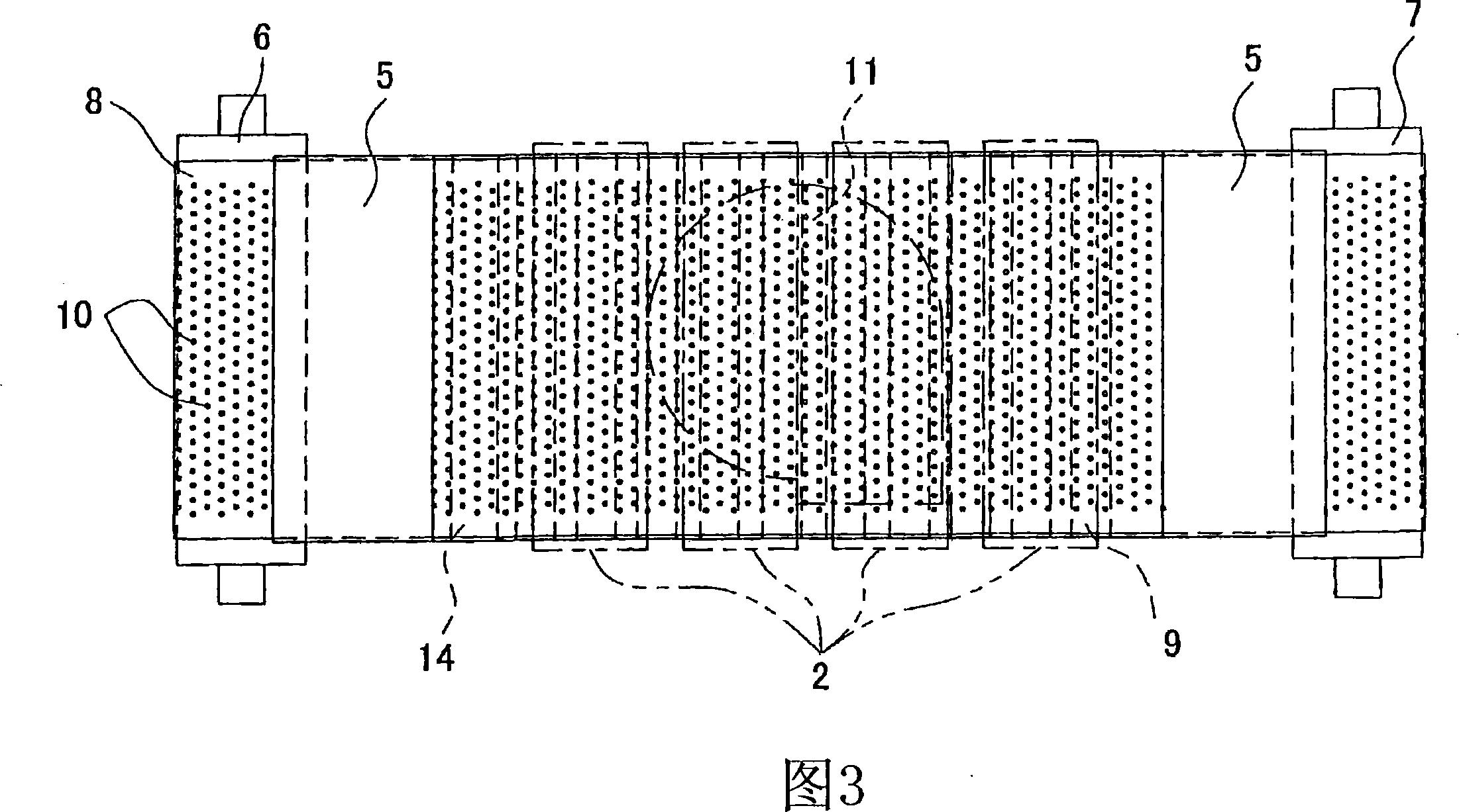
[0022] As shown in FIGS. 1 and 2 , the color inkjet printer 1 includes four print heads 2 , and a sheet conveying device 1 a including a conveyer unit 3 and a suction unit 4 .

[0023] The inkjet printer 1 may be a line printer including four print heads 2 each corresponding to four ink colors (for example, magenta, yellow, cyan, etc.) arranged in the sheet conveying direction. and black). Each of the four print heads 2 may have a hexahedral shape elongated in a direction perpendicular to the sheet conveyance direction. The bottom surface of the print head 2 faces the conveyance belt 8 . When the sheets P sequentially conveyed by the conveying belt 8 pass under the print head 2 , ink droplets of each color are ejected to a printing area defined on the ...


PUM


Abstract

A sheet conveying device may include a belt, a fan, and a housing, the belt has a plurality of through holes, the fan is arranged so that a portion of the belt at a return running position intervenes between the fan and the belt at a forward running position Between portions, the housing and the portion of the belt in the forward running position define a chamber. The fan creates negative pressure within the chamber by drawing air through the through holes of the endless belt, thereby removing dust and other unwanted particles and debris from the endless belt. In one or more examples, brushes may also be included to provide further removal of unwanted dust and particles. Additionally, in one or more configurations, the sheet transport device may further include belt rollers and / or supports.

Description

[0001] Cross References to Related Applications [0002] This application claims priority from Japanese Patent Application No. 2006-260067 filed on September 26, 2006, the disclosure of which is hereby incorporated by reference in its entirety. technical field [0003] Embodiments relate to sheet conveying devices configured to convey sheets. Background technique [0004] Current systems include sheet transport devices that include a belt mechanism configured to transport recording media and a platen disposed adjacent an inner surface of a belt of the belt mechanism. In this sheet conveying device, the belt of the belt mechanism is moved by a pair of rollers in a running (ie conveying) direction. The belt is formed of an air-permeable or air-permeable foam material. The platen has suction openings and a suction fan to generate negative pressure inside the platen. The recording medium is conveyed by the belt while being sucked or pulled toward the surface of the belt throu...

Claims


Application Information

Patent Timeline
Patent Type & Authority Applications(China)
IPC IPC(8): B41J11/00B41J13/00B65H5/22B65H5/02
CPCB65H5/224B65H2406/3124B65H11/005B41J11/007B41J11/0085B65H2301/531
Inventor 坂井田惇夫
Owner BROTHER KOGYO KK
Why Eureka
Try Eureka