Imaging device

A technology for a camera device and a camera element, which is applied to projection devices, printing devices, focusing devices, etc., can solve the problems of difficulty in zooming and focusing on miniaturization.

Inactive Publication Date: 2008-04-02
FUJI PHOTO OPTICAL CO LTD
View PDF3 Cites 26 Cited by
  • Summary
  • Abstract
  • Description
  • Claims
  • Application Information

AI Technical Summary

Problems solved by technology

[0006] However, in such an imaging device, since the hand-shake correction mechanism and the imaging optical system are integrally moved in the direction of the optical axis, it is necessary to provide a space in the imaging device for actuating these components.
For this reason, it is difficult to sufficiently miniaturize an imaging device equipped with a hand-shake correction mechanism for zooming and focusing

Method used


Image

  • Imaging device
  • Imaging device
  • Imaging device

Examples


Embodiment Construction

[0020] Hereinafter, embodiments of the present invention will be described with reference to the drawings. In addition, in the description of the drawings, the same reference numerals are attached to the same elements, and overlapping descriptions are omitted.

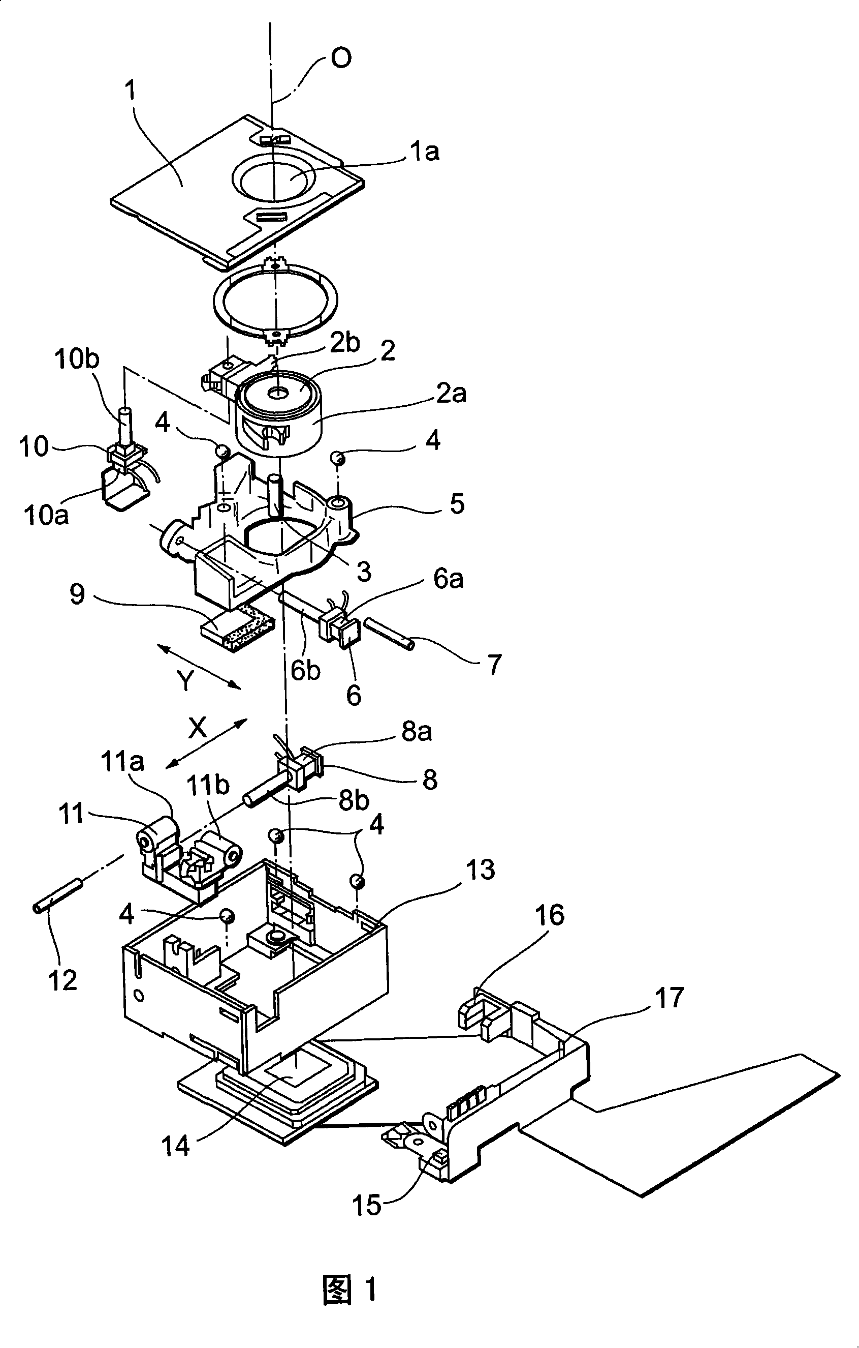
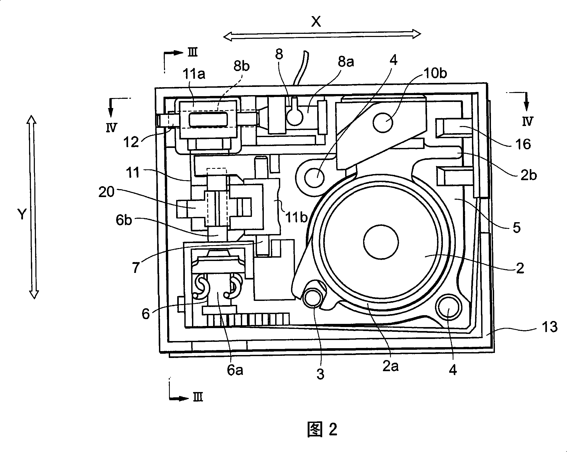
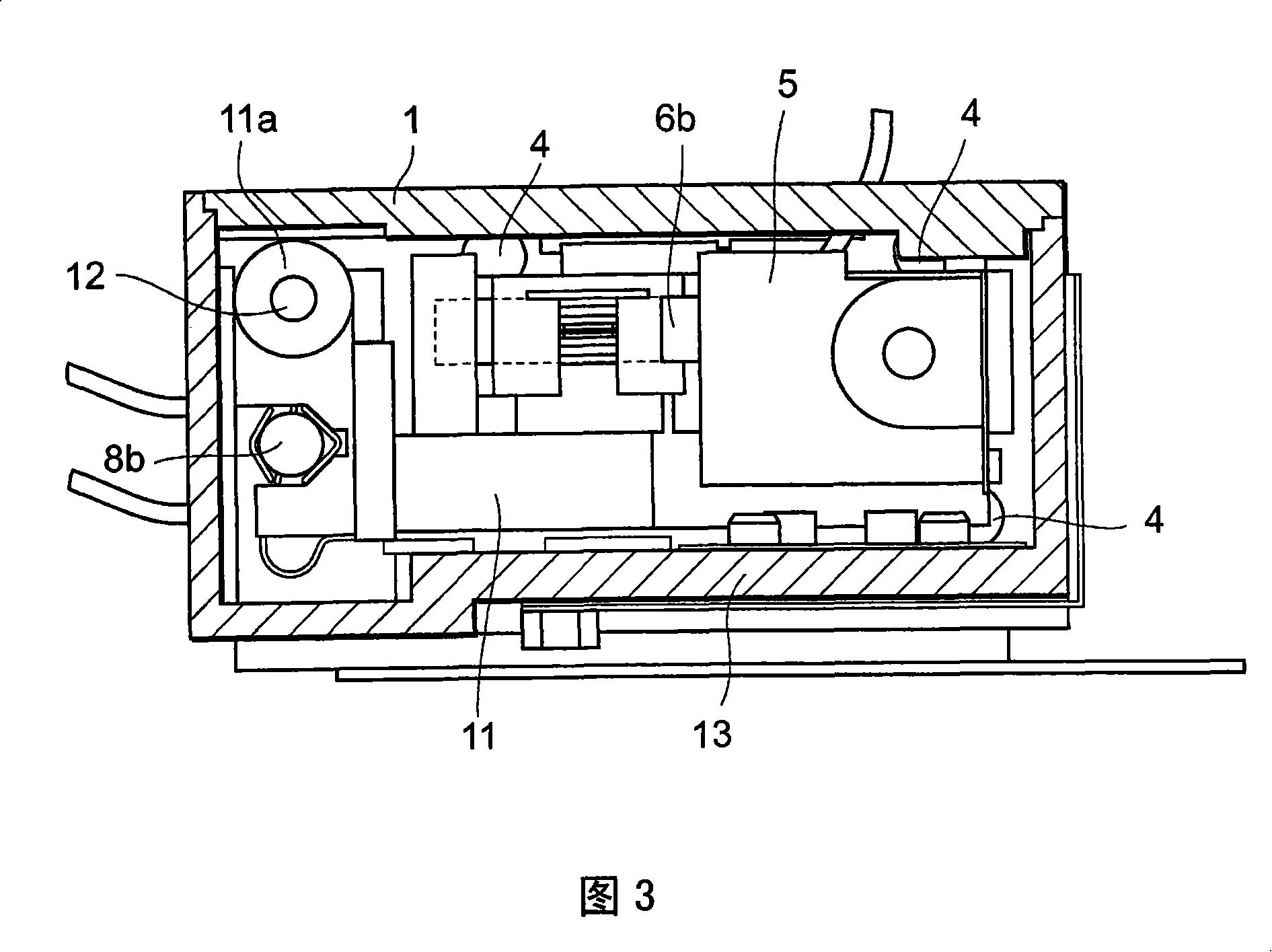
[0021] 1 is an exploded perspective view of an imaging unit, a camera shake correction mechanism, and a zoom mechanism in an imaging device according to an embodiment of the present invention. 2 is a plan view of an imaging unit and a hand-shake correction mechanism of the imaging device according to the present embodiment. Fig. 3 is a sectional view of III-III in Fig. 2 . Fig. 4 is a sectional view taken along line IV-IV of Fig. 2 .

[0022] In the imaging device according to the above aspect, camera shake correction is performed by relatively moving the imaging optical system and the imaging element in a direction perpendicular to the optical axis direction. That is, the camera shake is corrected by moving the ima...


PUM


Abstract

An imaging device for making camera shake compensation by relatively moving an imaging optical system and an imaging element in directions perpendicular to an optical axis direction, includes first to third actuators and a moving member. The first actuator relatively moves the imaging optical system and the imaging element in a first direction perpendicular to the optical axis direction. The second actuator 6 relatively moves the imaging optical system and the imaging element in a second direction which is perpendicular to the optical axis direction and which intersects the first direction. The second actuator is attached to the moving member. The moving member is moved by an action of the first actuator and an action of the second actuator in the first direction and the second direction. The third actuator relatively moves the imaging optical system and the moving member in the optical axis direction.

Description

technical field [0001] The present invention relates to an imaging device used for photographing. Background technique [0002] Conventionally, among video cameras, video cameras, and video cameras mounted on mobile phones, there has been known an imaging device equipped with a function of correcting hand shake during shooting to zoom or focus (for example, Patent Document 1). This imaging device is a device that integrates an imaging optical system and a hand-shake correction mechanism and moves in an optical axis direction to perform zooming or focusing. [0003] [Patent Document 1] Japanese Unexamined Patent Publication No. 10-39350 [0004] [Patent Document 2] JP-A-2005-309209 [0005] [Patent Document 3] JP-A-2005-33 No. 1399 [0006] However, in such an imaging device, since the hand-shake correction mechanism and the imaging optical system move integrally in the direction of the optical axis, it is necessary to provide a gap in the imaging device for actuating thes...

Claims


Application Information

Patent Timeline
Patent Type & Authority Applications(China)
IPC IPC(8): G03B5/00H04N5/232H04N101/00
CPCG02B27/646H04N5/2254G03B17/02G02B5/3025H04N5/2253H04N5/23248G03B3/10G03B5/00G03B2205/0061H04N23/55H04N23/54H04N23/68H04N23/00
Inventor 铃木祐亮
Owner FUJI PHOTO OPTICAL CO LTD
Why Eureka
Try Eureka