
Screw fastening structure with high-strength self-forming screw

A technology for threaded parts and fastened connections, applied in the field of threaded fastening structures, can solve problems such as mass production and unrealistic costs, and achieve the effect of improving fatigue strength

Active Publication Date: 2011-04-20
TOPURA CO LTD
View PDF2 Cites 4 Cited by
  • Summary
  • Abstract
  • Description
  • Claims
  • Application Information

AI Technical Summary

Problems solved by technology

However, the value of the pitch error used in this method needs to be managed in units of μm, and this method is also unrealistic in terms of mass production and cost
Therefore, the status quo is that there are basically no effective methods for achieving an increase in the fatigue limit

Method used


Image

  • Screw fastening structure with high-strength self-forming screw
  • Screw fastening structure with high-strength self-forming screw
  • Screw fastening structure with high-strength self-forming screw

Examples


Embodiment Construction

[0019] Preferred embodiments of the present invention will be clarified by describing below with reference to the accompanying drawings.

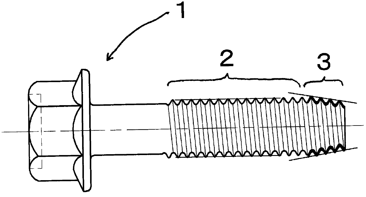
[0020] figure 1 It is the self-forming threaded part 1 used in the present invention, which is made by roll forming before heat treatment, and has a strength of 14T (the minimum tensile strength is 1400N / mm 2 , Hardness of 44 ~ 47HRC) steel threaded parts. Its threaded part is composed of a tapered self-forming part 3 and a common parallel threaded part 2 for fastening connection. The self-forming part 3 is formed in the range of 1 to 5 pitches and is configured to its maximum outer diameter Or the imaginary outer diameter is 1 to 10% larger than the outer diameter of the external thread of the parallel thread portion 2 . The imaginary outer diameter means, for example, the diameter of a cylinder imaginary drawn by the tip of the protrusion when the self-forming part 3 is formed by providing a protrusion on the threaded part. In additio...


PUM


Abstract

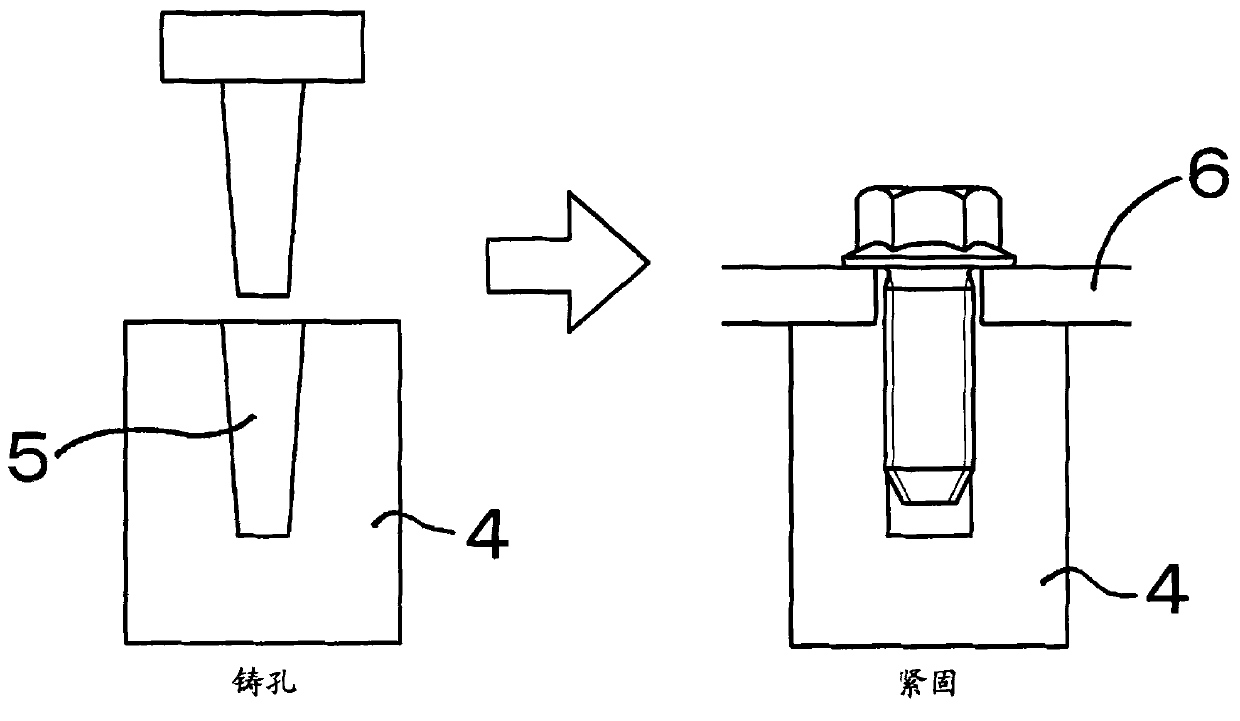
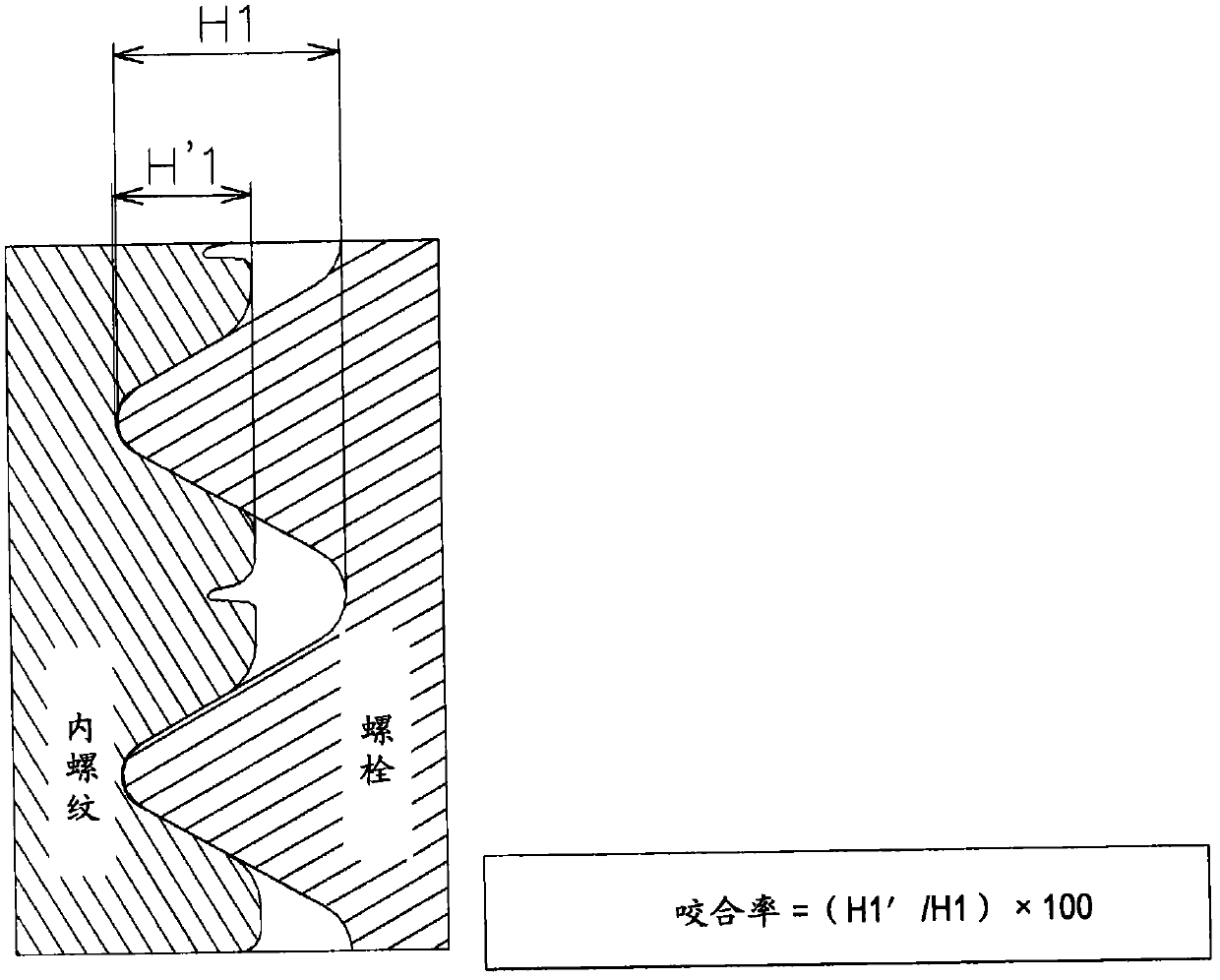
To provide a screw fastening structure for enhancing the strength of a bolt and fatigue strength by reducing the machining process without altering the shape of an associated member, and for achieving downsizing by keeping the fitting length of a thread almost the same as that of the prior art, thus contributing remarkably to weight reduction of a vehicle. A self-forming screw (1) having a strength 14T produced by form rolling before heat treatment is employed as a fastening bolt, and the self-forming screw is driven into a member (4) having an as-cast, nonthreaded rough hole (5). In a screw fastening structure to which a fixing member (6) is fastened, the catch rate of a female screw and a male screw formed by a self-form is 75-90%, the fitting length of the screw and the rough hole is d-2.5d (d is screw diameter), and no clearance appears at the contact surface of the male and female screws because of self-forming screw fastening.

Description

technical field [0001] The present invention relates to a threaded fastening structure for fastening using high-strength self-forming threaded parts (bolts). Background technique [0002] Conventionally, in a threaded connection structure for fastening and connecting parts around the engine using high-strength bolts, the high-strength bolts are screwed into the internal threads of nuts or internal threads tapped on mating parts. use. The internal thread portion of such a nut or a tapped internally threaded hole is of course formed by cutting. For example, when forming internally threaded holes in cast aluminum parts around the engine, chassis or underbody parts, forged parts, etc. Figure 7 As shown, it is necessary to carry out casting holes (or forging hole processing) for matching parts such as die-casting parts, pre-drilling processing with a drilling machine, pre-drilling cleaning, tapping processing, and threaded hole cleaning. process. [0003] In addition, attempt...

Claims


Application Information

Patent Timeline
Patent Type & Authority Applications(China)
IPC IPC(8): F16B5/02F16B25/06
CPCF16B25/00F16B25/0021Y10T403/75
Inventor 森茂人马田明英松野真弓
Owner TOPURA CO LTD
Learn More