Design aiding system and design aiding method
An auxiliary system and design drawing technology, applied in computing, image data processing, instruments, etc., can solve problems such as longer construction period, high possibility of misordering, time-consuming, etc., and achieve high building efficiency, shorten construction period, and reduce costs Effect
- Summary
- Abstract
- Description
- Claims
- Application Information
AI Technical Summary
Problems solved by technology
Method used
Image

Examples
Embodiment Construction
[0038] An embodiment of the present invention will be described below with reference to the accompanying drawings.
[0039] In addition, the structure described below does not limit this invention, Various changes are possible within the scope of the spirit of this invention.
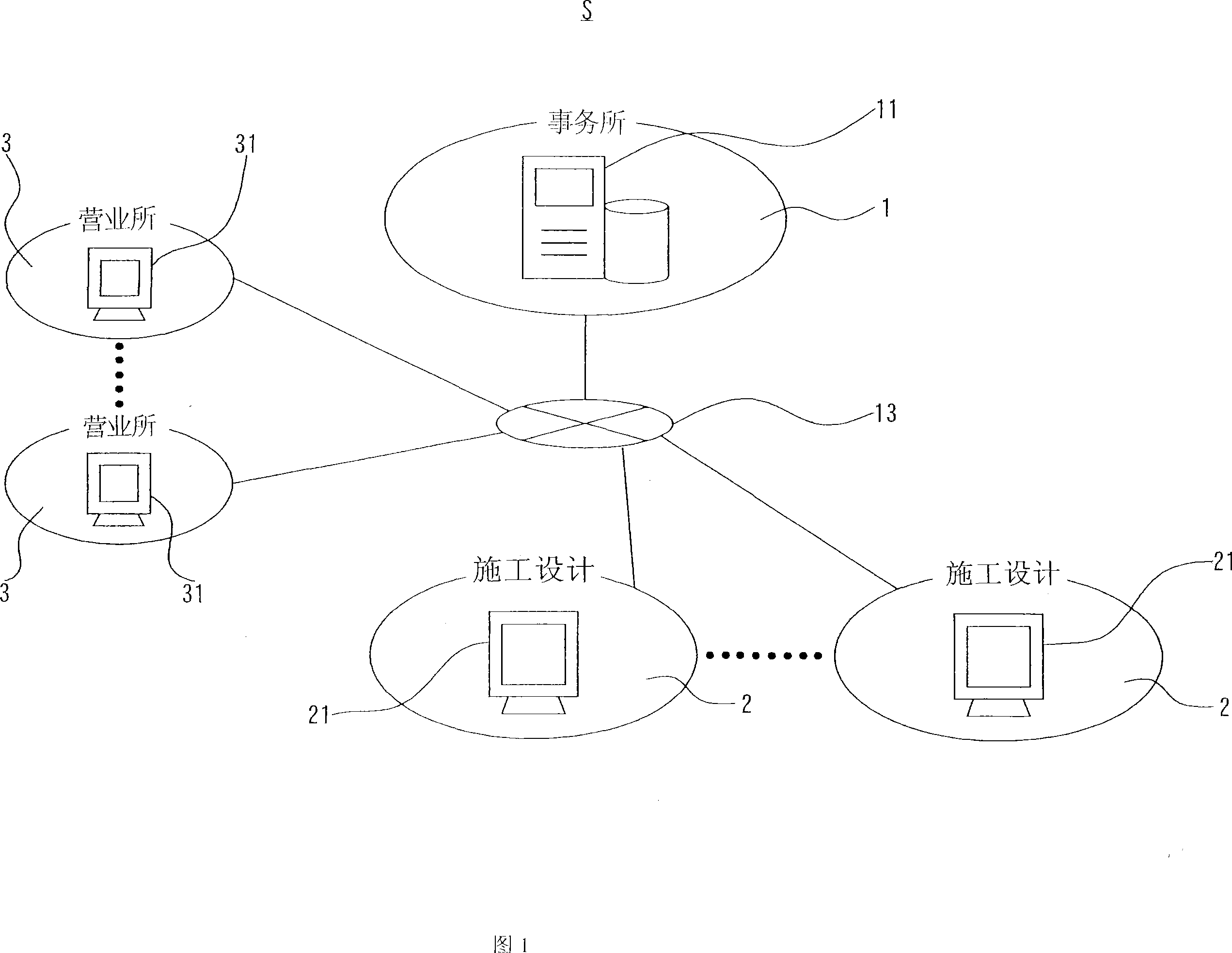
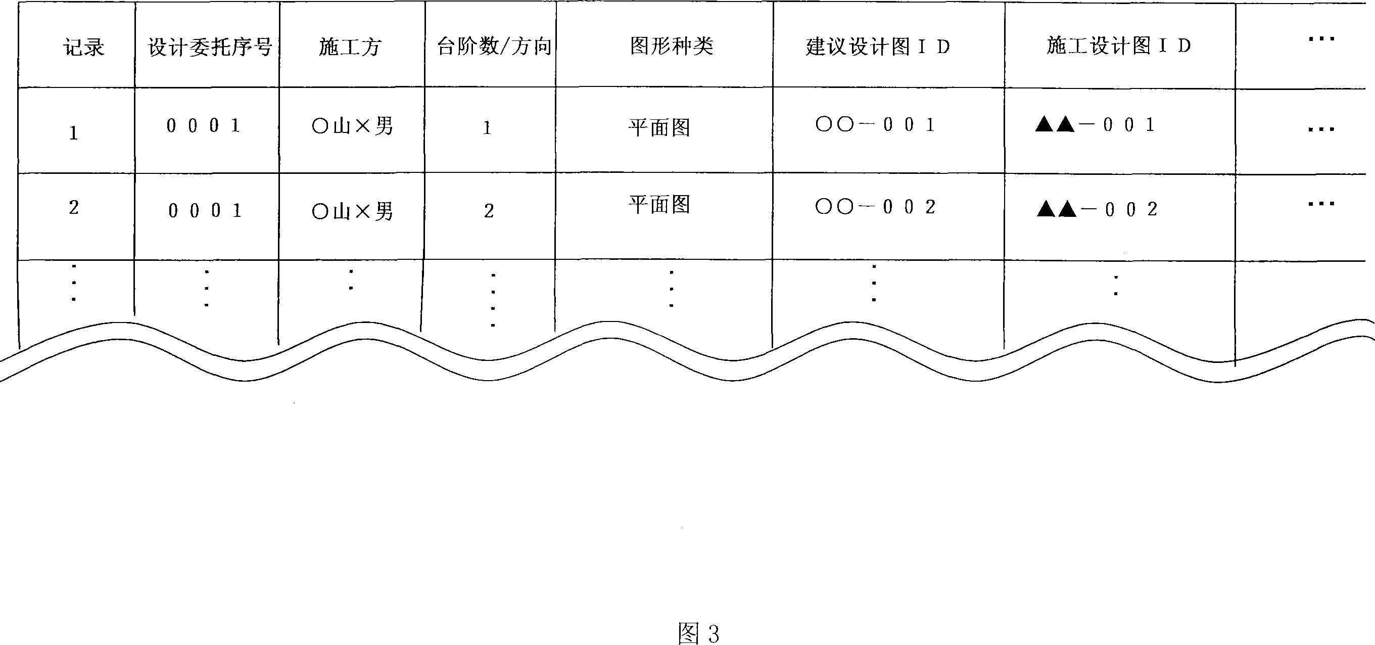
[0040] This embodiment relates to a design support system S capable of deriving detailed information on a building from a suggested design drawing presented to a customer, and submitting the information to a process of preparing components and components constituting a building.
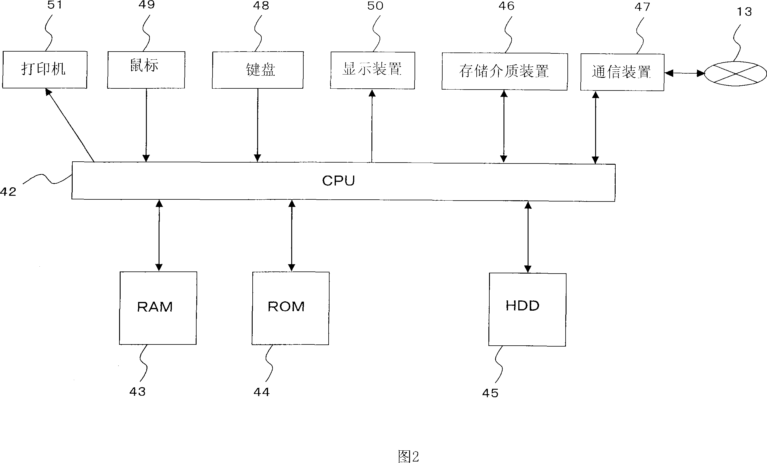
[0041] The term "computer" in this specification means to include all information terminals having computing devices.
[0042] For example, in addition to supercomputers, general-purpose computers, office computers, control computers, workstations, and personal computers, mobile phones including portable information terminals and computing devices are also included.
[0043] In addition, although the Internet line 13 is used ...
PUM
 Abstract
Description
Claims
Application Information
 - Generate Ideas
- Intellectual Property
- Life Sciences
- Materials
- Tech Scout
- Unparalleled Data Quality
- Higher Quality Content
- 60% Fewer Hallucinations
Browse by: Latest US Patents, China's latest patents, Technical Efficacy Thesaurus, Application Domain, Technology Topic, Popular Technical Reports.
© 2025 PatSnap. All rights reserved.Legal|Privacy policy|Modern Slavery Act Transparency Statement|Sitemap|About US| Contact US: help@patsnap.com