Vortex spinning machine and spinning method

A spinning machine and flow-feeding technology, which is applied to spinning machines, open-end spinning machines, and continuous winding spinning machines, etc., can solve the problem of wear of rubber rollers and aprons, and the difference in drafting speed and spinnability. Long distance, short service life and other problems, to achieve the effect of reducing wear consumption, eliminating roving process and increasing spinning speed

Inactive Publication Date: 2010-09-29
JIANGNAN UNIV
View PDF5 Cites 0 Cited by
  • Summary
  • Abstract
  • Description
  • Claims
  • Application Information

AI Technical Summary

Problems solved by technology

However, in order to achieve a super large draft of 120 to 150 times, the air-jet spinning roller drafting mechanism must implement the process route of "tight gauge, heavy pressure, zero nip, strong control" in production, and the rubber roller is usually at 2000r The high speed of about / min and the unconditional rotation of the drafting strand under the heavy pressure of the front roller will inevitably cause serious wear and short service life of the rubber roller and rubber ring. For example, the average service life of ordinary rubber rollers is One week, the average service life of the special Japanese Teijin rubber rollers is only one and a half months, making the production cost of air-jet spinning high
At the same time, although the drafting mechanism has achieved super-large drafting of the strands, the drafting speed is still far from the spinnability of the airflow in the twister at a rotation speed of 500,000 to 1,000,000 revolutions / min, which restricts the speed of air-jet spinning. further improvement of
[0003] The latest Murata vortex spinning machine has a spinning speed as high as 450m / min. The unique mechanism ensures high-speed and reliable yarn forming. However, the drafting form it adopts is still roller drafting, and there is no fundamental adjustment to the drafting form. change, and thus restrict the further improvement of its spinning speed

Method used


Image

  • Vortex spinning machine and spinning method
  • Vortex spinning machine and spinning method
  • Vortex spinning machine and spinning method

Examples


Embodiment Construction

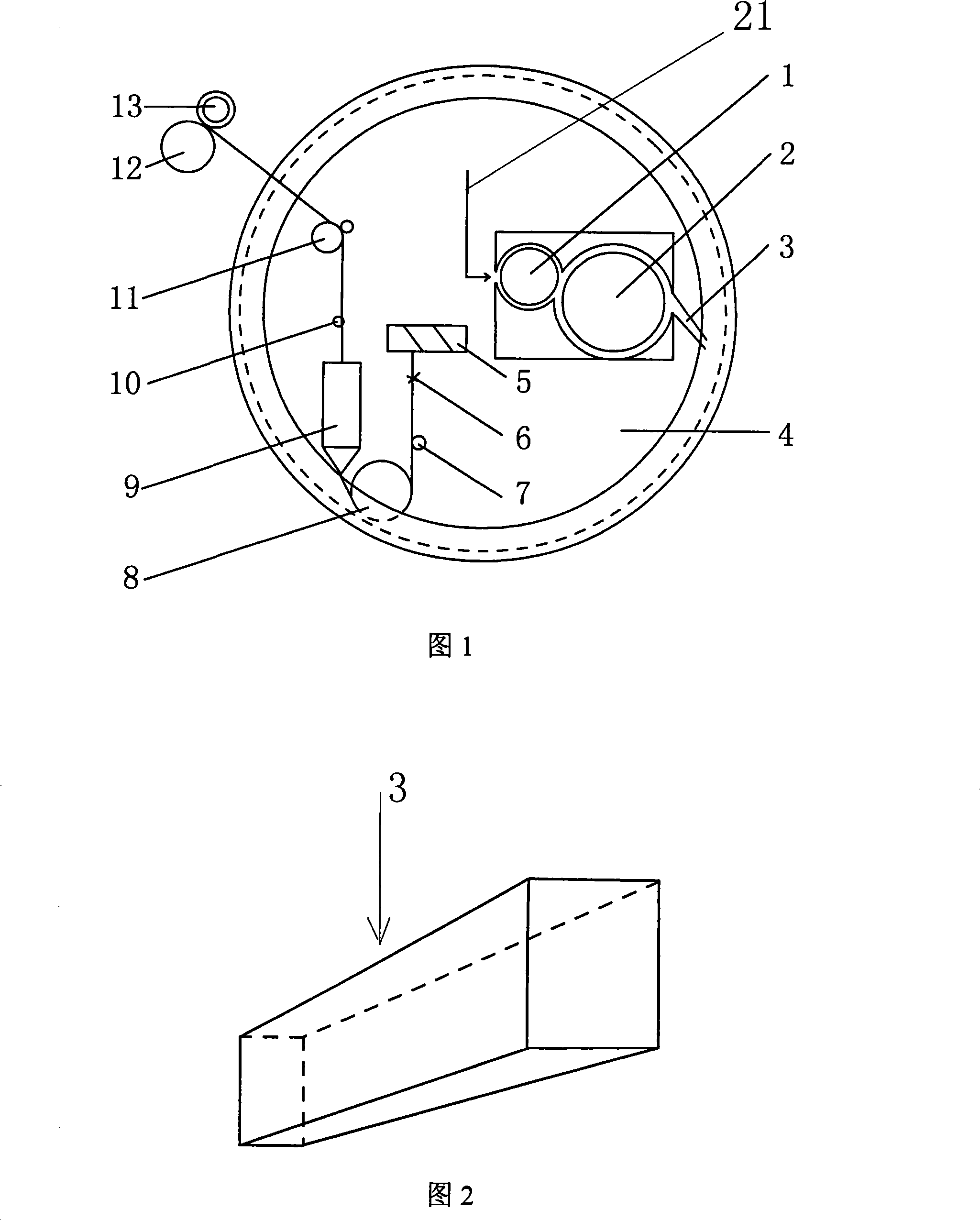
[0015] like figure 1 As shown: in the direction of travel of the sliver 21, a cotton feeding device 1, a comb roller drafting mechanism 2, a tapered fiber conveying mechanism 3, a closed fiber collecting device 4, a swirl twister 9 and a yarn roll are arranged in sequence Winding device; the filament frame 5, tension device 6, yarn guide 7 and pressing roller 8 are arranged in sequence in the direction of filament travel; stretching mechanism 2, and then enter the closed fiber gathering device 4 through the tapered fiber conveying mechanism 3 for drafting, merging and gathering to form fiber strips, and then send them into the swirl twister with the rotation of the closed fiber gathering device 4 9; At the same time, after the core filament drawn from the filament rack 5 passes through the tension device 6, it is sent to the swirl twister 9 through the yarn guide 7 and the pressing roller 8; the fiber thin strips are swirled together with the core filament Twisted by device 9...


PUM


Abstract

The invention relates to a spinning machine, in particular to a swirling spinner. According to the technical proposal of the invention, a cotton feeder, a carding roller drafting mechanism, a gradual withdrawing fiber conveying mechanism, a closed fiber collecting device, a swirling stranding machine and a winding device are arranged in sequence along the direction of the movement of cotton slivers; a long wire frame, a tensile device, a wire guider and a pressing roller are arranged along the direction of the movement of long wires; cotton slivers led from a sliver can first go through the cotton feeder and the carding roller drafting mechanism and then enters the closed fiber collecting device through the gradual withdrawing fiber conveying mechanism for drafting, integrating and clustering to form fiber strip which is then sent to the swirling stranding machine along with the rotation of the closed fiber collecting device; and meanwhile, core wires led from the long wire frame are sent to the swirling stranding machine through the wire guider and the pressing roller after going through the tensile device. The swirling spinner spares easily worn spinning parts and employs air flow to act on fibers, which fully activates high efficiency of swirling stranding machine and thus improves spinning rate.

Description

technical field [0001] The invention relates to a spinning machine, in particular to a rotary spinning machine. Background technique [0002] Air-jet spinning is a spinning method that uses high-speed rotating airflow to twist the strands. The spinning speed is 200-400m / min. Unique yarn structure and other characteristics. Most of the drafting forms are three-roller or four-roller double-short apron drafting or three-roller long and short apron drafting. The drafting components include rollers, rubber rollers, rubber rings, lower pins, strip guides, clusters, and cradles. However, in order to achieve a super large draft of 120 to 150 times, the air-jet spinning roller drafting mechanism must implement the process route of "tight gauge, heavy pressure, zero nip, strong control" in production, and the rubber roller is usually at 2000r The high speed of about / min and the unconditional rotation of the drafting strand under the heavy pressure of the front roller will inevitabl...

Claims


Application Information

Patent Timeline
Patent Type & Authority Patents(China)
IPC IPC(8): D01H4/02
Inventor 葛明桥李永贵顾闻彦朱立成
Owner JIANGNAN UNIV
Why Eureka
Try Eureka