Slurry bed reactor and Fischer-Tropsch synthesis method

A reactor and slurry bed technology, applied in the field of hydrocarbon synthesis, can solve the problems of severe catalyst wear, difficult gas-solid separation, and affecting operation

Pending Publication Date: 2019-10-29
CHNA ENERGY INVESTMENT CORP LTD +1
View PDF6 Cites 2 Cited by
  • Summary
  • Abstract
  • Description
  • Claims
  • Application Information

AI Technical Summary

Problems solved by technology

The Fischer-Tropsch synthesis slurry bed reactor requires the particle size of the catalyst to be between 20-100 microns, otherwise the catalyst and the product cannot form a slurry phase. and gas phase product) separation problem
[0007] Especially with the progress of the reaction, the wear of the catalyst is getting worse, the average particle diameter is getting smaller and smaller, the gas-solid separation is getting more and more difficult, and the solid entrainment is serious, which affects the subsequent operation

Method used


Image

  • Slurry bed reactor and Fischer-Tropsch synthesis method
  • Slurry bed reactor and Fischer-Tropsch synthesis method
  • Slurry bed reactor and Fischer-Tropsch synthesis method

Examples


Embodiment approach

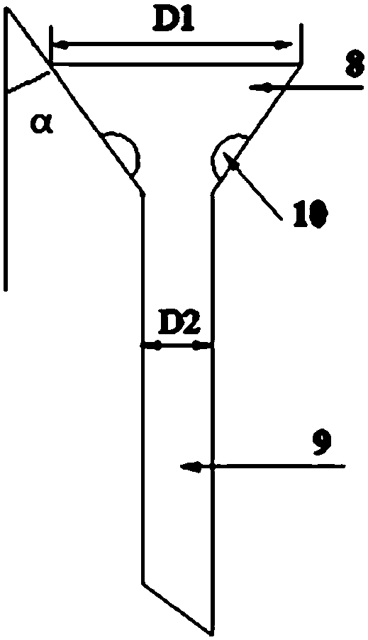
[0037] According to the present invention, it is only necessary to ensure that the degassing liquid collecting and guiding part has a funnel-shaped opening section, and there is no special requirement for a specific funnel-shaped form. According to a preferred embodiment of the present invention, the funnel-shaped opening Section 8 is tapered.

[0038] According to the present invention, the arrangement form of the diversion pipe section can be diversified, and it can be a pipe with a reduced diameter, a pipe with the same diameter, a square pipe, or a round pipe.

[0039] According to a preferred embodiment of the present invention, the diversion pipe section 9 is a straight circular pipe for diversion.

[0040] According to a more preferred embodiment of the present invention, the ratio of the diameter D1 of the tapered circular opening to the diameter D2 of the directing straight tube is 3-10.

[0041] According to the present invention, the bearing force of the degassing ...

Embodiment 1

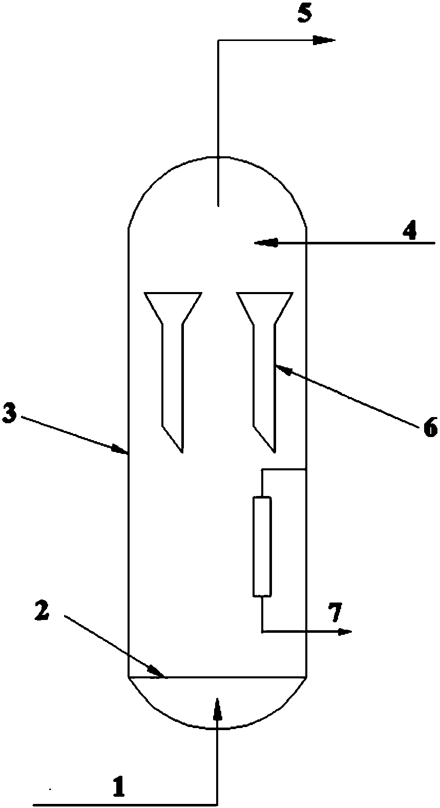
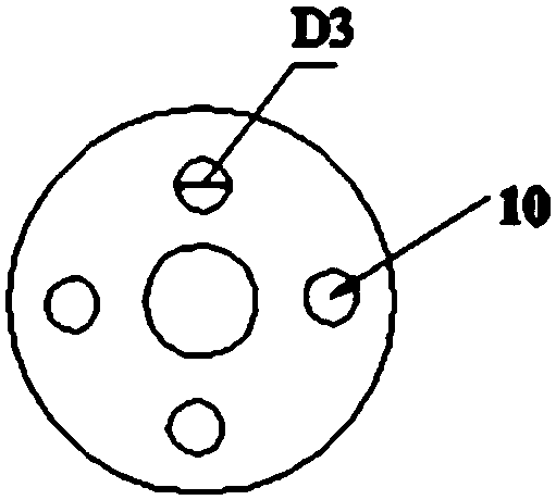
[0067] The inner diameter of the Fischer-Tropsch synthesis slurry bed reactor is 5m, and the total height of the reactor is 45m. The upper and lower layers of the slurry bed reactor are equipped with degassing liquid collection and diversion parts. The upper part of the degassing liquid collection and diversion part is conical and the lower part is Straight diversion pipe, the angle between the axis of the tapered section and the busbar is 30°, 6 diversion holes are uniformly arranged on each degassing liquid collection and diversion part, and there are 48 degassing liquid collection and diversion parts in total, each 24 layers, wherein D1=0.5m, D2=0.15m, D3=0.08m, the height ratio of the diversion pipe section 9 to the funnel-shaped opening section 8 is 5:1; The total height is 3m, with the inlet section as the starting position, the first layer of degassing liquid collecting and guiding parts is set at 23-26m of the reactor, and the second layer of degassing and liquid collec...


PUM

PropertyMeasurementUnit
heightaaaaaaaaaa
particle size distributionaaaaaaaaaa
particle sizeaaaaaaaaaa

Abstract

The invention relates to the field of hydrocarbon synthesis and specifically provides a slurry bed reactor and a Fischer-Tropsch synthesis method. The reactor comprises a reactor inlet section, a gasdistributor, a reaction section and a gas-liquid-solid separation section arranged from bottom to top; a solid-liquid separator communicating with a liquid product outlet of the reactor is arranged below the middle inside the reaction section; a plurality of degassing, liquid collecting and diversion parts are arranged above the middle inside the reaction section; and each of the degassing, liquidcollecting and diversion parts comprises a funnel-shaped open section and a diversion pipe section communicating from top to bottom. Compared with the prior art, the reactor provided by the inventionis capable of obviously improving the performances of a catalyst when being applied to a gas-liquid-solid three-phase reaction, and the wear and consumption of the catalyst are obviously reduced.

Description

technical field [0001] The invention relates to the field of hydrocarbon synthesis, in particular to a slurry bed reactor and a Fischer-Tropsch synthesis method. Background technique [0002] With the continuous rise of oil prices in recent years, people pay more and more attention to the development of technologies to produce alternative oil products. Syngas is produced through coal, natural gas or other substances, and then according to the requirements of the Fischer-Tropsch synthesis catalyst for synthesis gas, through water-gas shift and synthesis The gas purification process processes the syngas, and uses the treated syngas as a raw material to produce hydrocarbons through Fischer-Tropsch synthesis, and at the same time produces oxygenated compounds, which are then processed by mature petroleum processing technology to produce high-quality, environmentally friendly oil. Taste. The development of Fischer-Tropsch synthesis technology is of great significance to the deve...

Claims


Application Information

Patent Timeline
Patent Type & Authority Applications(China)
IPC IPC(8): B01J8/22C10G2/00
CPCB01J8/22C10G2/342C10G2/344
Inventor 杜冰卜亿峰佟瑞利赵用明孙永伟
Owner CHNA ENERGY INVESTMENT CORP LTD
Why Eureka
Try Eureka