Wire saw

A technology of wire saw machine and rope wheel, applied in the direction of stone processing tools, working accessories, manufacturing tools, etc., can solve the problems of discontinuous working time, low working efficiency, high production cost, etc., so as to improve the service life and reduce the probability of damage , the effect of reducing the chance of damage

Active Publication Date: 2017-07-18
陈立文
View PDF6 Cites 2 Cited by
  • Summary
  • Abstract
  • Description
  • Claims
  • Application Information

AI Technical Summary

Problems solved by technology

[0005] The purpose of the present invention is to overcome the defects of the prior art and provide a wire saw machine to solve the problem that some parts of the wire saw machine in the prior art are damaged when the cutting object falls, so as to ensure the safety of the whole machine and the diamond beaded rope. However, there are problems such as discontinuous working hours, troublesome maintenance, time-consuming maintenance, low work efficiency, and high production costs.

Method used


Image

  • Wire saw
  • Wire saw
  • Wire saw

Examples


Embodiment 1

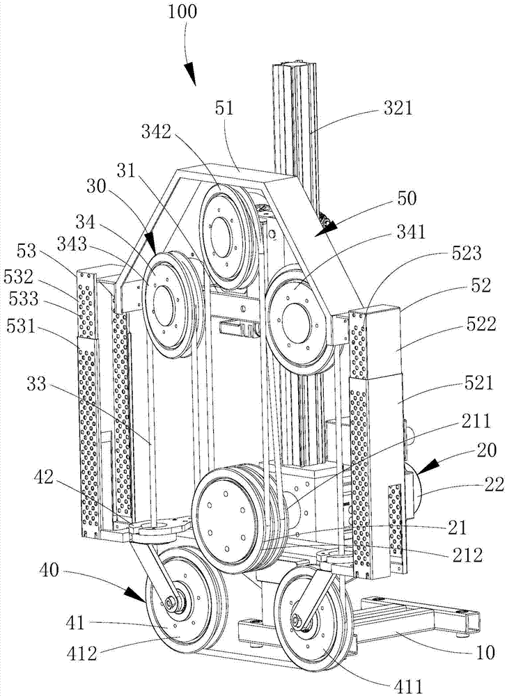
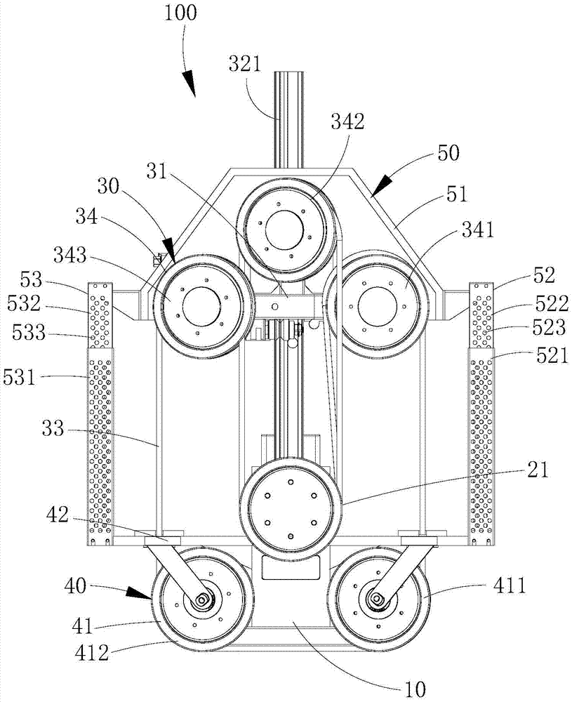
[0037] see Figure 1 to Figure 4 , The first embodiment of the wire saw machine of the present invention will be described below.

[0038] The wire saw machine 100 of this embodiment mainly cuts building concrete, marble blocks, etc.; and the wire saw machine 100 includes a mounting base 10, a driving assembly 20, a walking cutting unloading assembly 30 and a rope receiving assembly 40. Facing the various components of the wire saw machine 100 for further description:

[0039] The driving assembly 20 includes at least one driving wheel 21 and a first driving source 22 for driving the at least one driving wheel 21 to rotate. on, and be connected with at least one driving wheel 21;

[0040] The walking cutting and unloading assembly 30 includes a walking support 31 that can slide up and down above the mounting base 10, a lifting mechanism 32 for making the walking support 31 slide up and down, a diamond beaded rope 33 for cutting objects to be cut, and a diamond beaded rope 33 f...

Embodiment 2

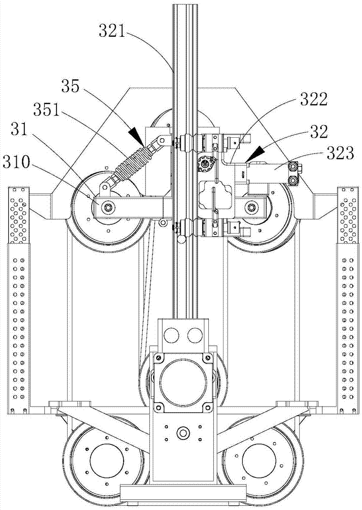
[0072] see Figure 5 and Image 6 , the implementation of Embodiment 2 is similar to that of Embodiment 1. For details, please refer to the description of Embodiment 1, which will not be described in detail here, and the difference between the two is:

[0073] In Embodiment 1, one end of the tension spring 351a is connected to the first support arm 311, and the other end of the tension spring 351a is connected to the rotating arm 310, and is close to the driven wheel 34 provided on the rotating arm 310, and pulls The centerline of the spring 351a coincides with the centerline of the rotating arm 310 located in the initial area C. As shown in FIG.

[0074] In the second embodiment, the walking frame 31 further includes a second support arm 312a, and the second support arm 312a is vertically arranged on the upper end of the first support arm 311;

[0075] One end of extension spring 351a is connected on the second support arm 312a, and the other end of extension spring 351a is...

Embodiment 3

[0077] see Figure 7 , the implementation of the third embodiment is similar to the implementation of the second embodiment. For details, please refer to the description of the second embodiment, which will not be described in detail here, but the difference between the two is:

[0078] In the second embodiment, the walking frame 31 further includes a second support arm 312a, and the second support arm 312a is vertically arranged on the upper end of the first support arm 311;

[0079] One end of the extension spring 351a is connected to the second support arm 312a, the other end of the extension spring 351a is connected to the rotating arm 310, and is close to the driven wheel 34 provided on the rotating arm 310, and the center line of the extension spring 351a is in line with the rotating arm 310. The central line of the rotating arm 310 when located in the initial region is sandwiched by an angle θ, and 0°<θ<90°.

[0080] In the third embodiment, the walking frame 31 also i...


PUM


Abstract

A wire saw (100) comprises an installation seat (10), a driving assembly (20), a travelling cutting unloading assembly (30) and a wire collecting assembly (40). The travelling cutting unloading assembly (30) comprises a travelling support (31), a lifting mechanism (32), a diamond string bead wire (33), at least one driven wheel (34) and an unloading mechanism (35), the travelling support comprises a rotary arm (310) and a first supporting arm (311) rotatably connected with the rotary arm (310), and the unloading mechanism comprises a restoring piece (351); and one end of the restoring piece (351) is connected to the travelling support (31), and the other end of the restoring piece (351) is connected to rotary arm (310). When external force acts on the driven wheels (34), the restoring piece (351) is driven by the rotary arm (310) to rotate from an initial area to a rotary area to remove acting force on the driven wheels (34) through the unloading restoring piece (351), the rotary arm (310) is returned to the initial area through the unloading restoring piece (351), and in this way, the problem that components of the wire saw (100) are damaged due to falling off of a cutted object is solved.

Description

technical field [0001] The invention relates to the technical field of cutting equipment, in particular to a wire saw machine. Background technique [0002] At present, some cutting equipment, such as wire saw machines, have the following problems: during the cutting process, when the building concrete is cut, the cut part will sink due to its own weight, such as the common concrete support When the beam is cut, dismantled or cut off, the removed concrete will sink and form a falling object, and the gravity of the falling object is very large, often several tons or even dozens of tons of gravity, so, according to this, The falling objects at this time will drive the diamond beaded rope and the machine to sink a few centimeters or ten centimeters together, and this situation will cause the diamond beaded rope to be pulled off, which will cause injuries to people and things, or cause machine damage and failure Frequent occurrence, so that the service life of the machine is gr...

Claims


Application Information

Patent Timeline
Patent Type & Authority Applications(China)
IPC IPC(8): B28D1/08B28D7/00
CPCB28D1/08B28D1/088B28D7/00
Inventor 陈立文
Owner 陈立文
Why Eureka
Try Eureka