Forming method of annular magnetic body orientating along the direction of radius or diameter radiation

A molding method and radiation orientation technology, which is applied in the manufacture of magnets, magnetic objects, permanent magnets, etc., can solve the problems of weakened orientation magnetic field strength, incomplete orientation of magnetic powder, high orientation degree, etc.

Active Publication Date: 2008-04-16
SHENZHEN RADIMAG TECH CO LTD
View PDF0 Cites 34 Cited by
  • Summary
  • Abstract
  • Description
  • Claims
  • Application Information

AI Technical Summary

Problems solved by technology

The biggest disadvantage of this method is that the degree of orientation is not uniform, some parts have high degree of orientation, and some parts have low degree of orientation
This method improves the uniformity of the orientation magnetic field to a certain extent. The biggest disadvantage is that when the inner diameter of the radiation ring is small, the intensity of the orientation magnetic field will be greatly reduced, so that the orientation of the magnetic powder is not complete (the first orientation method also has similar defects) , when the height of the radiation ring is high, not only the intensity of the orientation magnetic field weakens but also the uniformity becomes worse, all of which make the magnetic properties and consistency of the radiation ring worse

Method used


Image

  • Forming method of annular magnetic body orientating along the direction of radius or diameter radiation
  • Forming method of annular magnetic body orientating along the direction of radius or diameter radiation

Examples


specific Embodiment 1

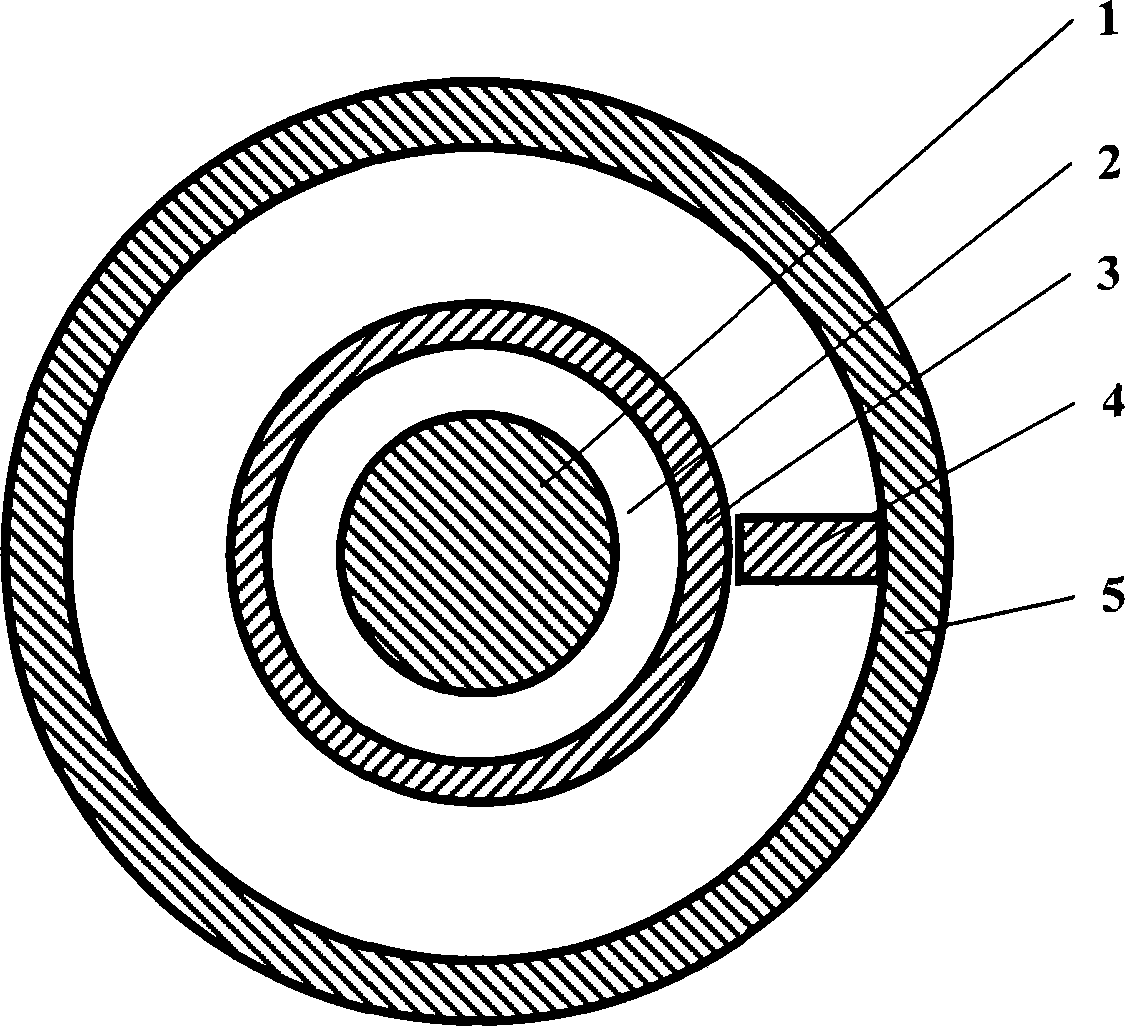
[0008] Specific embodiment 1: Use the inner magnetic pole-outer magnetic pole type orientation magnetic field to make a radiation ring

[0009] Combine figure 1 , When the two poles (N pole and S pole) of the magnetic field generated by the electromagnet or permanent magnet are introduced into the inner magnetic pole 1 and the outer magnetic pole 5 through a certain magnetic permeability device, the inner magnetic pole 1 and the outer magnetic pole magnetic sheet 4 A strong magnetic field is formed between. If the cavity 2 is filled with magnetic powder at this time, the magnetic powder in the magnetic field will be fully magnetized and oriented. If the outer magnetic pole magnetic sheet 4 is fixed on the outer magnetic pole 5, and the outer magnetic pole 5 is driven to rotate at a high speed by a motor, the magnetization and radiation orientation of all the magnetic powder in the cavity 2 can be realized. A gradual increase of pressure is applied to the magnetic powder in the ca...

specific Embodiment 2

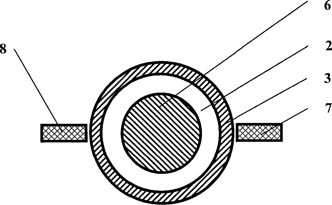
[0010] Specific embodiment 2: Use the outer magnetic pole-outer magnetic pole type orientation magnetic field to make a radiation ring

[0011] Combine figure 2 , When the two poles (N pole and S pole) of the magnetic field generated by the electromagnet or permanent magnet are introduced into the outer magnetic pole 7 and the outer magnetic pole 8 respectively through a certain magnetic permeability device, they will be between the magnetic core 6 and the outer magnetic pole 7 , Two strong magnetic fields are formed between the magnetic core 6 and the outer magnetic pole 8 at the same time. If the cavity 2 is filled with magnetic powder at this time, the magnetic powder in the two magnetic fields will be fully magnetized and oriented. The motor drives the outer magnetic pole 7 and the outer magnetic pole 8 to rotate at high speed at the same time to realize the magnetization and orientation of all the magnetic powder in the cavity 2. A gradual increase of pressure is applied to t...


PUM


Abstract

The invention discloses a method for forming a circular ring-shaped magnet of which the radiation orientation is along the radius direction or the diameter direction; the key points of the invention are that the oriented magnetic field is changed from the 360-degree distribution(or approximately 360-degree distribution) which is generally adopted at present to a very small part of 360 degrees of the radiation ring; the relative state between the magnetic powders in the forming process and the oriented magnetic field is changed from the relative rest(or approximately relative rest) which is generally adopted at present to the relative motion. The former mainly aims at getting larger oriented magnetic field and the latter aims at magnetizing and orienting the magnetic powders in a molding cavity at the 360-degree direction. The forming method of the invention can preferably resolve the technical problems generally existing in the making of the present radiation ring that the magnetic powders are not completely oriented due to the relatively low oriented magnetic field and the consistency of the magnetic performance of the radiation ring is not good due to the uneven distribution of the oriented magnetic field.

Description

Technical field [0001] The invention relates to a method for manufacturing an annular magnetic material, in particular to a method for forming an annular magnet oriented radially along the radius or diameter. technical background [0002] The toroidal magnet oriented along the radius or the diameter (radiation ring for short) has a wide range of application prospects in the field of electric motors. The biggest technical difficulty in making the radiating ring is the orientation method of the magnetic powder during the forming (or pressing) stage. At present, there are two main orientation methods used in the magnetic material industry: the first is the segmented orientation method. This molding method is to divide the ring into several parts, and introduce an orientation magnetic field into each part for orientation. The biggest shortcoming of this method is that the degree of orientation is not uniform, some parts have a high degree of orientation, and some parts have a low deg...

Claims


Application Information

Patent Timeline
Patent Type & Authority Applications(China)
IPC IPC(8): H01F41/02H01F7/00
CPCH01F41/028H01F41/0266
Inventor 成问好
Owner SHENZHEN RADIMAG TECH CO LTD
Why Eureka
Try Eureka