Network node detection method and apparatus

A network node and detection method technology, applied in the field of network communication, can solve the problems of high hardware speed and high cost of heartbeat messages, and achieve the effect of fast fault detection and low cost

Active Publication Date: 2008-04-16
NEW H3C TECH CO LTD
View PDF0 Cites 10 Cited by
  • Summary
  • Abstract
  • Description
  • Claims
  • Application Information

AI Technical Summary

Problems solved by technology

[0005] The problem to be solved by the embodiments of the present invention is to provide a network node detection method and device to solve the technical defects of high hardware speed requirements and high cost of heartbeat messages in the prior art

Method used


Image

  • Network node detection method and apparatus
  • Network node detection method and apparatus

Examples


Embodiment Construction

[0020] Below in conjunction with accompanying drawing and embodiment, the specific embodiment of the present invention is described in further detail:

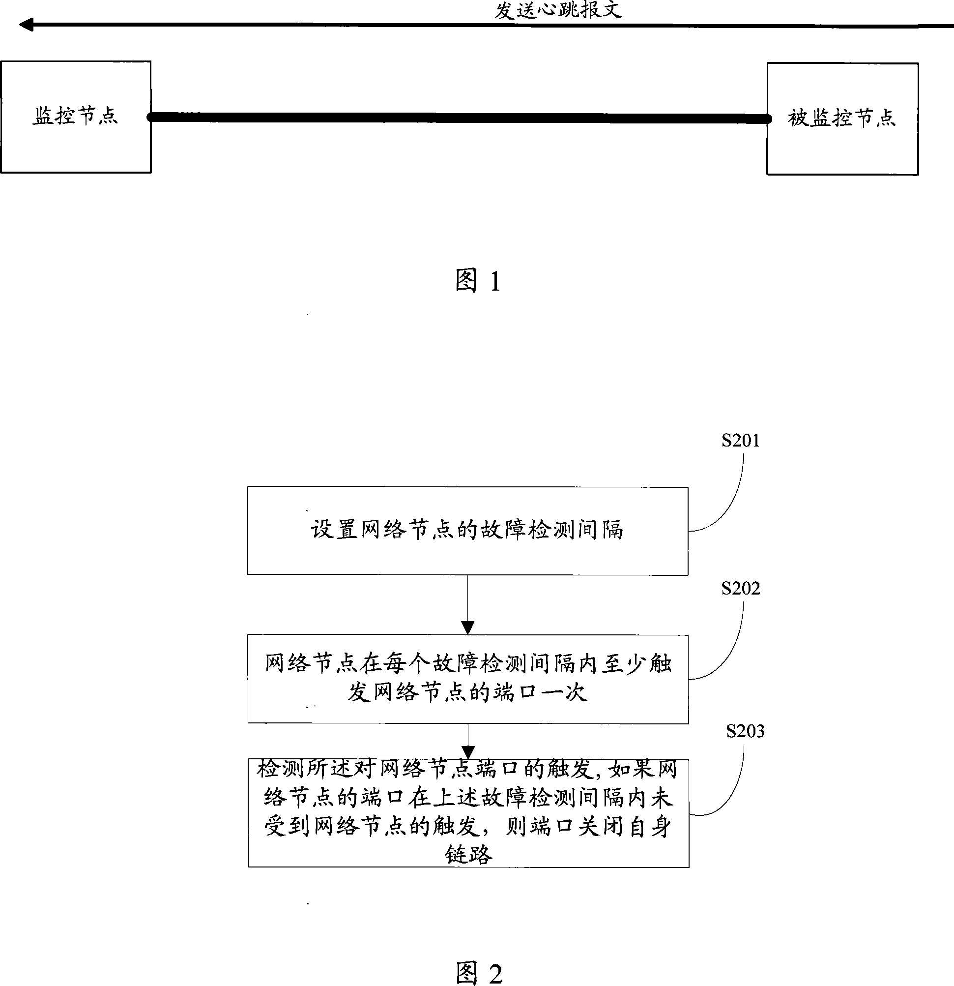
[0021] The embodiment of the present invention mainly lies in that after the port detects that a network node fails, it can automatically close the link of the port itself, thereby turning the network node failure into a link failure, so that the existing link failure detection technology can be used within milliseconds level to discover the faulty network node. Furthermore, the embodiment of the present invention also discloses a method for port detecting whether a network node is faulty, so as to ensure that the faulty node can be found within the time range specified by the operator.

[0022] As shown in Figure 2, it is a flowchart of a faulty node detection method in Embodiment 1 of the present invention, including the following steps:

[0023] Step S201, setting a fault detection interval U of a network node. For exampl...


PUM


Abstract

The invention discloses a failure node detection method, which comprise the steps: a failure detection interval U of the network node is arranged; the terminal of the network node at least is triggered once during each failure detection interval; the triggering at the terminals of the network nodes are detected; according to the detecting result, the failure of the network node is detected. The node failure of the network node is transformed into a link failure by the invention; the failure can be positioned in a millisecond by using the link failure detection technique of the prior art. The invention provides a failure detection method which is simple, highly efficient, low cost and quick in failure detecting.

Description

technical field [0001] The invention relates to the technical field of network communication, in particular to a network node detection method and device. Background technique [0002] With the continuous expansion of network scale, its complexity is getting higher and higher. At the same time, people's daily life and work are more and more dependent on the network. The ability to quickly solve problems is also becoming stronger. At present, the faults that occur in the network operation mainly include link faults and node faults. In order to recover quickly from network faults, faults must be found quickly and effectively. For carrier-class networks, a fault recovery time of 50ms is usually required, which includes not only the time for fault detection, but also the time for taking recovery measures. Therefore, it is required that faults must be found within a very short time, usually within 30ms. At present, the technology of link fault detection in the existing technolo...

Claims


Application Information

Patent Timeline
Patent Type & Authority Applications(China)
IPC IPC(8): H04L12/26H04Q3/00H04M3/22
Inventor 张雄
Owner NEW H3C TECH CO LTD
Why Eureka
Try Eureka