Secondary battery

A technology for secondary batteries and battery boxes, which is applied to battery pack components, battery covers/end covers, battery boxes/coatings, etc., and can solve problems such as reduced impact resistance, reduced strength of insulating rings, and damage to exhaust paths. Achieve the effects of preventing breakage, ensuring the total area, and high heat dissipation effect

Inactive Publication Date: 2008-04-16
PANASONIC CORP
View PDF3 Cites 5 Cited by
  • Summary
  • Abstract
  • Description
  • Claims
  • Application Information

AI Technical Summary

Problems solved by technology

[0009] Therefore, for the secondary battery with the structure shown in FIG. 9 and FIG. 10 , in the case of being impacted, as shown in FIG. In this case, there is the following problem: the insulating plate 36a on the side of the assembled sealing plate 35 is deformed under the impact force, and the air hole 38 formed on the filter 37 of the assembled sealing plate 35 is blocked by the insulating plate 36a, and the Possibility of escape of the resulting gas
[0010] On the other hand, with the structure of the battery disclosed in Patent Document 2, the movement of the plate group when receiving an impact is prevented to prevent the deformation of the lead wire, but due to the arrangement of the insulating ring, there is gas from the outer peripheral portion of the plate group. The problem that the exhaust path is damaged, if the insulating ring is notched to ensure the exhaust path, the strength of the insulating ring made of resin will be reduced, and the impact resistance effect will be reduced.
[0011] In addition, in the structure of the battery disclosed in Patent Document 3, the gas discharge path is ensured by providing a protrusion on the periphery of the vent hole of the metal sealing plate, but there is a problem that the movement of the electrode group when receiving an impact cannot be prevented. The problem, in addition, if the protrusion is increased to prevent movement, there is a problem that it will directly contact the plate group and cause a short circuit

Method used


Image

  • Secondary battery
  • Secondary battery
  • Secondary battery

Examples


Embodiment Construction

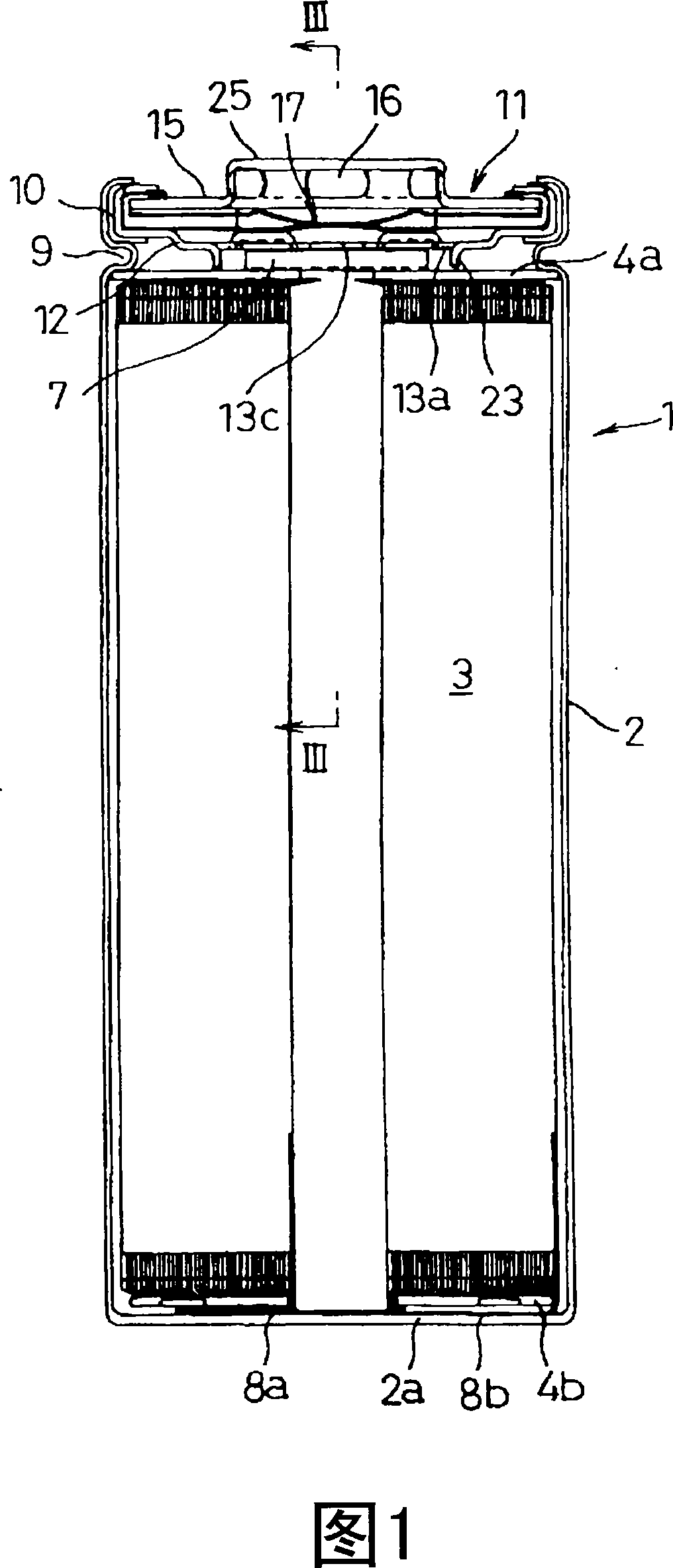
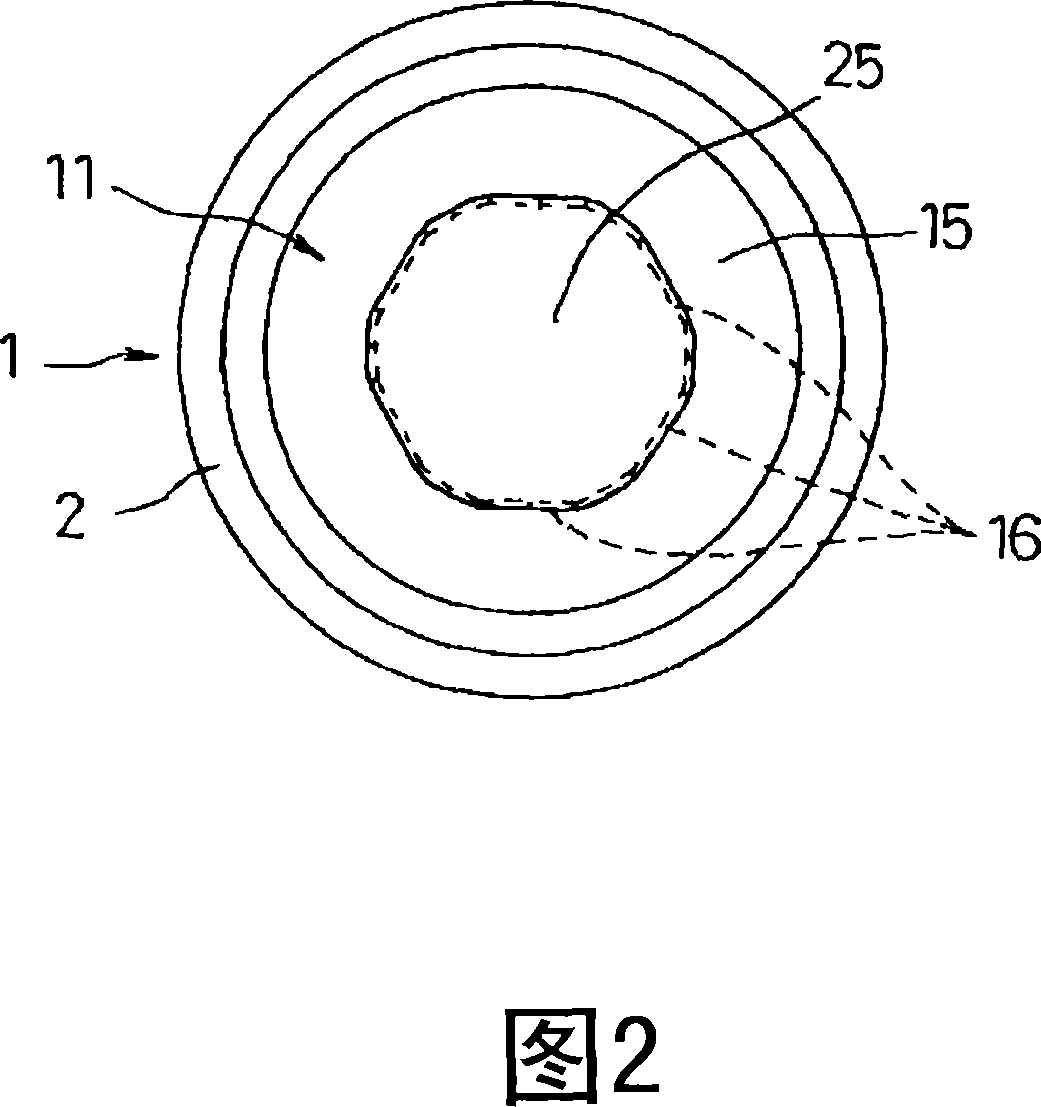
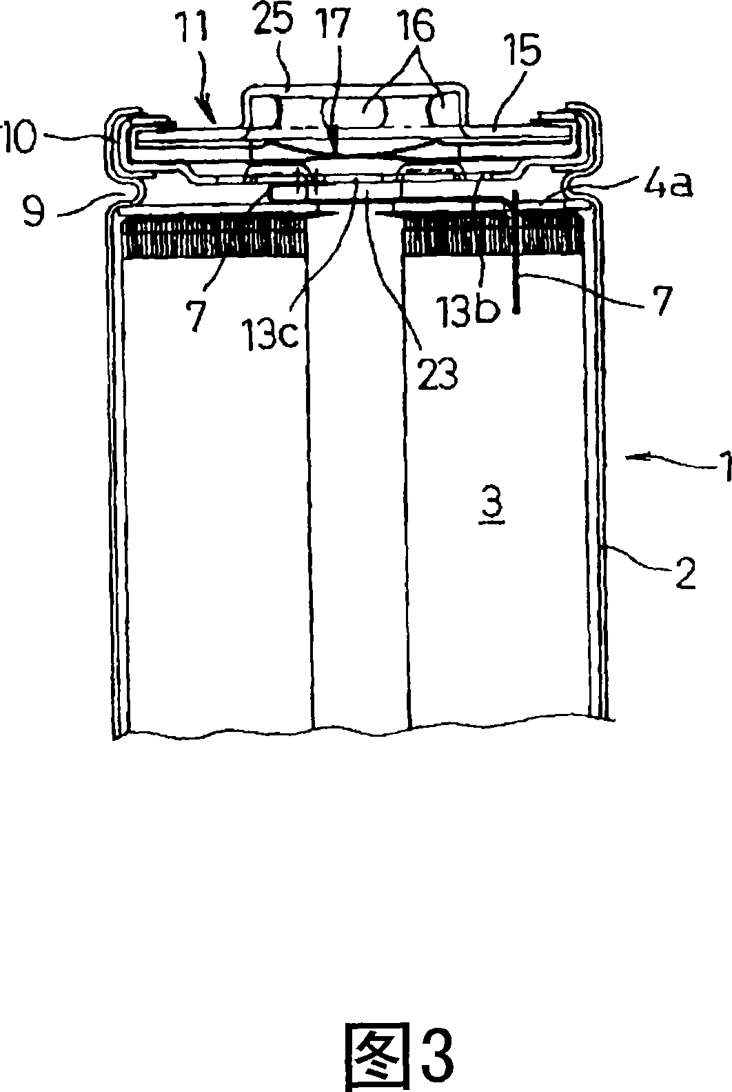
[0034] Hereinafter, an embodiment of the secondary battery of the present invention will be described with reference to FIGS. 1 to 8B.

[0035] In Figures 1 to 3, 1 is a cylindrical secondary battery composed of a lithium ion battery. A bottomed cylindrical battery box 2 contains an electrode group 3 as a power generation element together with electrolyte. . The electrode plate group 3 is formed by winding a strip-shaped positive electrode plate, a separator, a negative electrode plate, and a separator on the outer circumference of the core member in a state where they are sequentially stacked, and the core member is pulled out after the winding is completed. It is a structure in which a positive electrode plate and a negative electrode plate are laminated with a separator sandwiched between them. The separator protrudes up and down by an appropriate size from the positive electrode plate and the negative electrode plate. The upper and lower protrusions of the separator are bent r...


PUM


Abstract

In a secondary battery (1) comprising a battery case (2) for accommodating an electrode plate group (3) and an electrolyte, with one open end of the battery case (2) being sealed with an assembled sealing plate (11) that accommodates a safety mechanism (17) for exhausting pressure in the event of pressure build-up in the battery case (2) exceeding a predetermined level, at least one part (13a) of vent holes (13a, 13b, 13c) in the assembled sealing plate (11) facing the inside of the battery case (2) is constituted of an aperture that results from formation of a turned-out portion (23), the distal end of the turned-out portion (23) being allowed to abut on an insulating plate (4a) that makes contact with one end of the electrode plate group (3) so as to restrict movement of the electrode plate group (3). This can prevent malfunctioning due to displacement of the electrode plate group (3) when an impact or vibration is applied.

Description

Technical field [0001] The present invention relates to a secondary battery, and more particularly, to a secondary battery that prevents the occurrence of defects due to the movement of the electrode plate group caused by impact and vibration, and realizes the improvement of impact resistance. Background technique [0002] As a secondary battery such as a lithium ion battery and a nickel-hydrogen battery, there is known a secondary battery 31 having the following structure: as shown in FIG. 9, a bottomed cylindrical battery box 32 contains a pole plate as a power generation element The opening of the battery box 32 and the electrolyte are sealed with an assembly sealing plate 35 via an insulating gasket 34, and a lead of one polarity (not shown) extending from one end of the plate assembly 33 is connected To the assembly sealing plate 35, a wire (not shown) of another polarity extending from the other end of the electrode plate group 33 is connected to the inner bottom surface of...

Claims


Application Information

Patent Timeline
Patent Type & Authority Applications(China)
IPC IPC(8): H01M2/12H01M2/04H01M2/26H01M50/536H01M50/538
CPCH01M2/1229H01M2/263H01M2/0225Y02E60/12Y02E60/10H01M50/56H01M50/325H01M50/538H01M50/536H01M50/30H01M50/147
Inventor 桥本达也井上广树神月清美平川靖
Owner PANASONIC CORP
Why Eureka
Try Eureka