
Material separating disc for impact sand production machine

A technology of material distribution tray and sand making machine, which is applied in the direction of grain processing, etc., which can solve the problems of increased replacement cost and shortened service life, and achieve the effect of reducing loss, reducing impact and wear, and facilitating crushing

Inactive Publication Date: 2008-04-23
SHANGHAI JIANSHE LUQIAO MASCH CO LTD
View PDF0 Cites 2 Cited by
  • Summary
  • Abstract
  • Description
  • Claims
  • Application Information

AI Technical Summary

Problems solved by technology

Since the convex surface 2 is often impacted and worn by the material, the service life will be shortened, that is, the replacement cost will be increased

Method used


Image

  • Material separating disc for impact sand production machine
  • Material separating disc for impact sand production machine

Examples


Embodiment Construction

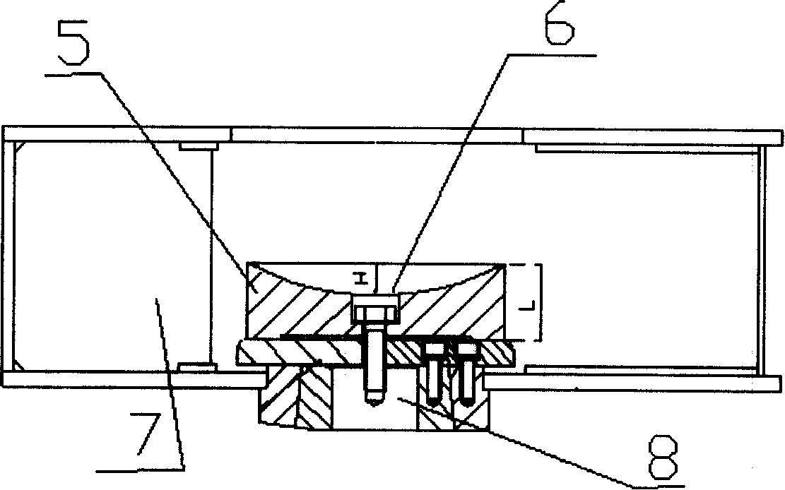
[0009] figure 2 It is a structural schematic diagram of the concave material distribution tray designed by the present invention. The upper part of the distribution tray 5 adopts a concave surface 6, the distribution tray 5 is fixed on the rotor 7, and the rotor 7 is fixed on the shaft system 8. The concave surface 6 can adopt a spherical concave surface or other arc concave surfaces, and can also adopt other regular or irregular concave surfaces as required.

[0010] The concave height of the concave surface 6 ( figure 2 H) accounts for the thickness of the entire distribution tray ( figure 2 1 / 3-2 / 5 of L), so that when the material falls to the distribution tray, some material will be accumulated on the concave surface 6, which acts as a material pad. When the material continues to fall, it will fall on the accumulated On the material, the distribution plate is not easy to wear, because the accumulated material plays a role in protecting the distribution plate. Using t...


PUM


Abstract

The present invention discloses a separatory disk for impact sand-making machine. It can reduce loss of separatory disk, and further reduce cost of separatory disk, besides, it is favourable for crushing. The described separatory disk is fixed on the rotor, the upper portion of the separatory disk is made into the form of concave surface, the described concave surface is a spherical concave surface, and the height of the described concave surface is 1 / 3-2 / 5 of whole separatory disk thickness.

Description

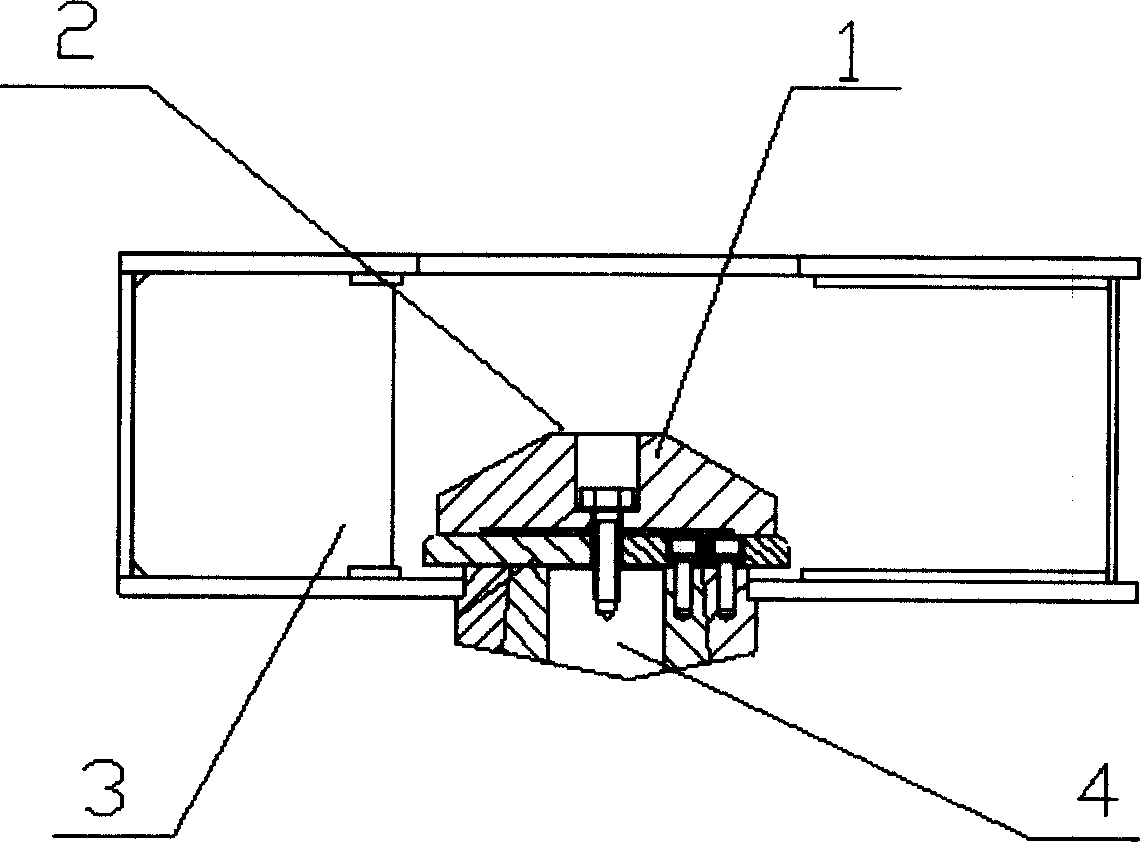
technical field [0001] The invention relates to an impact sand making machine, in particular to a material distribution tray applied to the impact sand making machine. Background technique [0002] As the material distribution plate in the impact sand making machine or vertical impact crusher plays the role of redirecting the material, it is generally made into a convex shape, but the convex material distribution plate is easily worn and has a short life due to the impact of the material. Such as figure 1 As shown, the distribution tray 1 is fixed on the rotor 3, and the rotor 3 is fixed by the shaft system 4, and the upper part of the distribution tray 1 is a convex surface 2. Since the convex surface 2 is often impacted and worn by materials, the service life will be shortened, that is, the replacement cost will be increased. Contents of the invention [0003] The technical problem to be solved by the present invention is to provide a distributing pan applied to impact...

Claims


Application Information

Patent Timeline
IPC IPC(8): B02C19/00
Inventor 郑鸣皋
Owner SHANGHAI JIANSHE LUQIAO MASCH CO LTD
Learn More