
Dual cartridge temperature control valve

a temperature control valve and cartridge technology, applied in the direction of valve housings, fluid pressure control, instruments, etc., can solve the problems of difficult cleaning and maintenance of control valves, difficulty in repairing and replacing control valve components, time and labor,

Inactive Publication Date: 2018-06-05
PROFIRE ENERGY
View PDF18 Cites 1 Cited by
  • Summary
  • Abstract
  • Description
  • Claims
  • Application Information

AI Technical Summary

Benefits of technology

The present invention has various technical effects such as replacing trim components without removing the bonnet or packing, using dual quad ring seals, and not requiring loading of the packing box or stuffing box. Additionally, the trim includes integrated, dual-seal characteristics with both hard seal and soft seal features for improved seal and increased life of the trim. Furthermore, a plug with a quad ring seal can create a dual seal with the metal and rubber reducing impact and wear between the metal plug and the metal seat.

Problems solved by technology

However, there are a number of disadvantages to control valves currently used in the industry.
One disadvantage is that repairing and replacing control valve components is often difficult and time and labor intensive.
Cleaning and maintaining control valves may also be difficult for similar reasons.
Another problem is that commonly occurs in control valves currently used in the industry is wearing of a plug and seat from the continual battering of the plug against the seat as the control valve opens and closes.
Also, packing or stuffing used in control valves wear out and may lose their elasticity or shape over time.

Method used


Image

  • Dual cartridge temperature control valve
  • Dual cartridge temperature control valve
  • Dual cartridge temperature control valve

Examples


Embodiment Construction

[0022]The invention and accompanying drawings will now be discussed so as to enable one skilled in the art to practice the present invention. The drawings and descriptions are exemplary of various aspects of the invention and are not intended to narrow the scope of the appended claims.

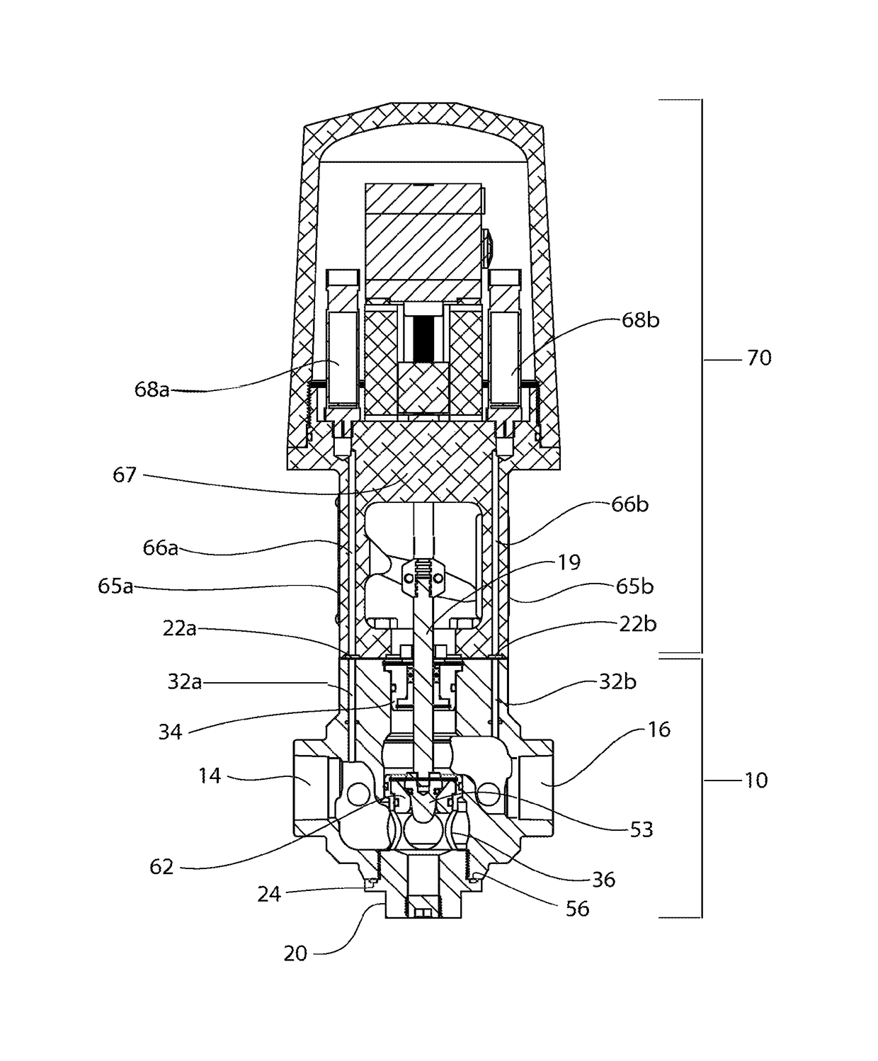
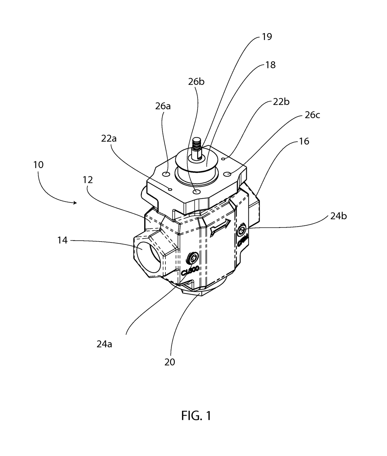
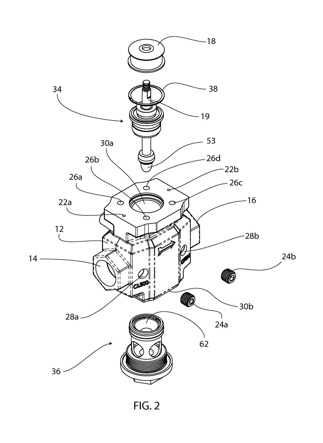
[0023]Turning now to FIG. 1 through 3, a temperature control valve 10 in accordance with one or more aspects of the present invention is shown. As shown in FIGS. 1 through 3, the control valve 10 may be comprised of a valve body 12, a bonnet cartridge 34, and a seat cartridge 36. As seen in FIG. 1, the control valve body 12 has a fuel entrance port 14 and a fuel exit port 16. The valve body 12 may also be configured with a bonnet manifold 30a in a top section of the valve body 12 for receiving a bonnet cartridge 34 in accordance with the present invention. The valve body may also be configured with a seat cartridge manifold 30b in a bottom section of the valve body 12 for receiving a seat cartridge in ...


PUM


Abstract

A dual cartridge temperature control valve having a self-contained, top loading bonnet cartridge and a self-contained, bottom loading seat cartridge. The control valve body may include internally configured pressure channels configured to mate with the upstream and downstream pressure channels of a control valve actuator having internally integrated pressure channels.

Description

PRIORITY[0001]The present application claims the benefit under 35 U.S.C. § 119 (e) of each of U.S. Provisional Patent Application Ser. No. 61 / 870,691 entitled “Temperature Control Valve Actuator Assembly” filed on Aug. 27, 2013 and U.S. Provisional Patent Application Ser. No. 61 / 870,776 entitled “Dual Cartridge Temperature Control Valve” filed on Aug. 27, 2013, each of which is incorporated herein by reference in its entirety.THE FIELD OF THE INVENTION[0002]The present invention relates to control valves for use in a valve train. More specifically, the present invention relates to a novel dual cartridge temperature control valve used in valve trains for a combustion application at an oil or gas well site.BACKGROUND[0003]Combustion applications are commonly used at oil and gas well sites in association with heater tanks, separators, treaters, amine re-boilers, and line heaters. Fuel being supplied to a burner unit or pilot in a combustion application is commonly channeled through a v...

Claims


Application Information

Patent Timeline
Patent Type & Authority Patents(United States)
IPC IPC(8): F16K27/00G05D16/20F16K41/02F16K31/04G05D7/06F16K27/08
CPCF16K27/00F16K31/04F16K41/02G05D16/202G05D7/0635Y10T137/7761F16K27/08Y10T137/7758F16K37/005F16K1/36F16K1/46
Inventor LOVELESS, MARK R.PARKS, MELVIN HALHATCH, JUSTIN W.
Owner PROFIRE ENERGY
Learn More