
Ratchet screw handle torsion structure

A grip and ratchet technology, which is applied to wrench, wrench, screwdriver, etc., can solve the problems of affecting the pivoting effect or positioning effect, easy to accumulate dust, and unsightly appearance design, so as to achieve good positioning effect and reduce the number of handles. The effect of volume and extended moment arm

Inactive Publication Date: 2008-04-23
胡厚飞
View PDF0 Cites 1 Cited by
  • Summary
  • Abstract
  • Description
  • Claims
  • Application Information

AI Technical Summary

Problems solved by technology

[0007] The object of the present invention is to provide a ratchet screwdriver handle twist structure, the technical problem to be solved is that the tool handle of the existing structure The outer surface is concave-convex and undulating, which is not only unsightly in appearance, but also more likely to accumulate dust in the depressions, which will affect the pivoting effect or positioning effect

Method used


Image

  • Ratchet screw handle torsion structure
  • Ratchet screw handle torsion structure
  • Ratchet screw handle torsion structure

Examples


Embodiment Construction

[0029] Regarding the technology, means and effects used in the present invention, a preferred embodiment is given and described in detail below with drawings, which are for illustration purposes only, and are not limited by this structure in the patent application.

[0030] refer to Figure 5 and Image 6 , the handle 1 of the present invention includes a first handle 10, a second handle 20 and a positioning device 30; one end of the second handle 20 is pivotally arranged on one end of the first handle 10, and can be positioned by the positioning The device 30 is torsionally positioned between a first position and a second position. in:

[0031] Please cooperate with the reference Figure 7 , the first handle 10 has a first end and a second end, and the first end is provided with a chamber 11 for screwing a cover 15 , thereby accommodating several screwdriver bits 16 . The second end of the first handle 10 is formed with an inclined end surface 12 , and the end surface 12 ...


PUM


Abstract

The present invention relates to a ratchet screwdriver handle turning structure. It includes a first handle, a second handle and a positioning device. One end of the described first handle is formed into an end face, on the described end face a shaft portion is set, the described shaft portion has two containing grooves; one end of the described second handle is formed into a glide plane with pivot connection portion, the described pivot connection portion is pivoted on the described shaft portion, and the described second handle can be turned relatively to first handle between first position and second position, the described pivot connection portion has a through hole extended from the second handle to exterior, and said through hole has a positioning groove correspondent to a containing groove; the described positioning device possesses two positioning components and a control component, the described two positioning components are respectively contained in said two containing grooves, and the described two positioning components are respectively pushed by an elastic body and bias-fed into the positioning groove of said through hole, the described control component is mounted in the described through hole and is used for pushing the positioning component aligned with positioning groove and making the positioning component be fed into the containing groove.

Description

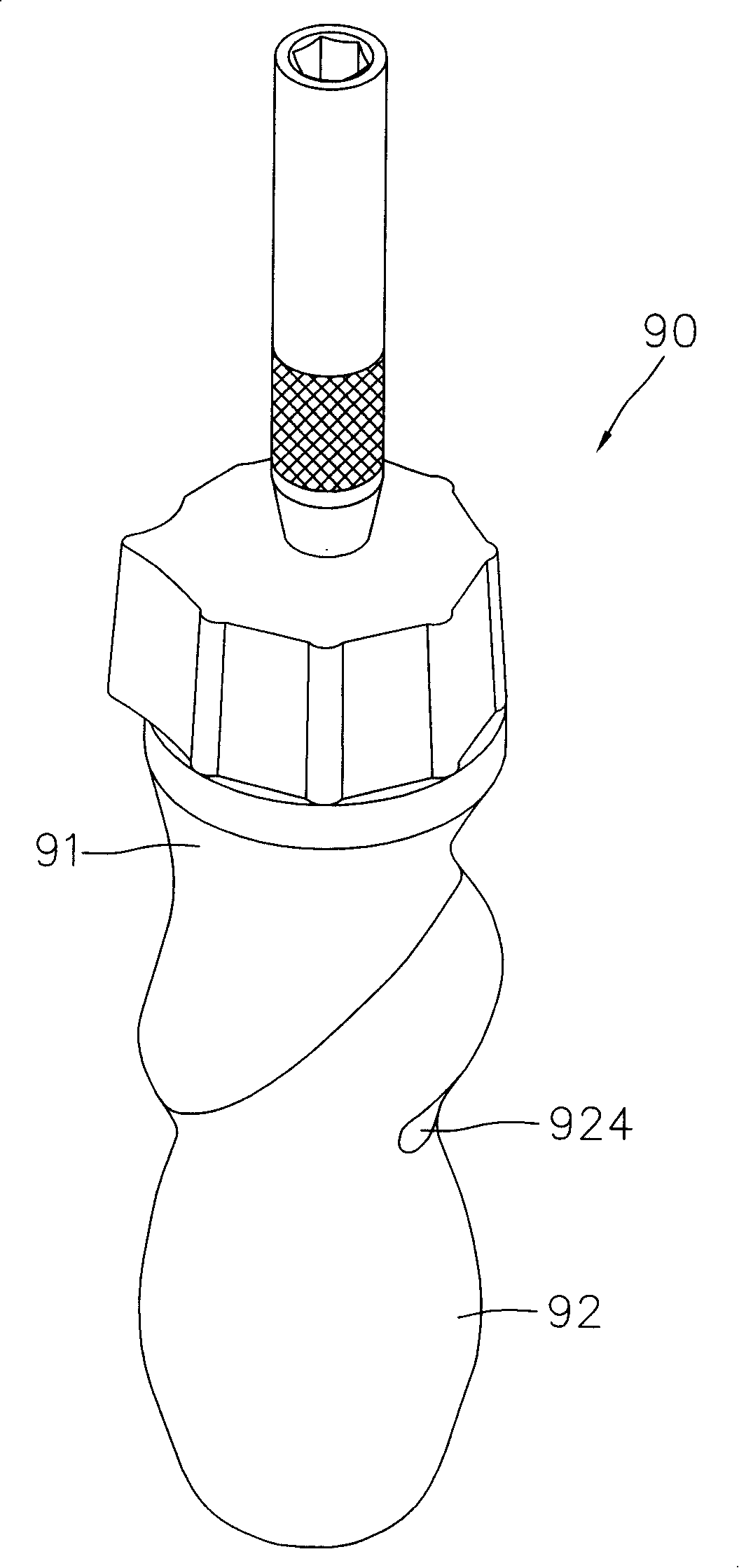
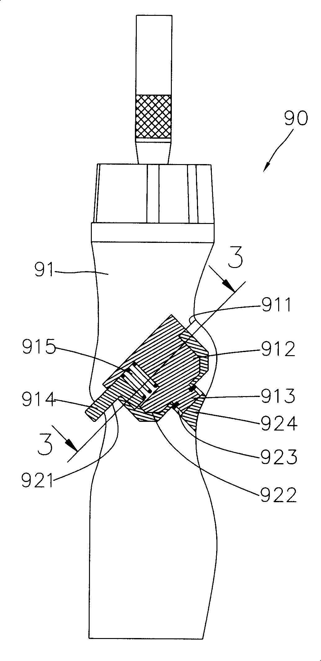
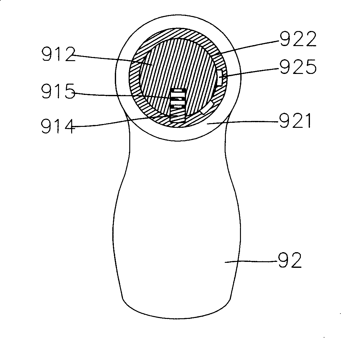
technical field [0001] The invention relates to a twisting structure of a handle of a ratchet screwdriver, in particular to a twisting structure of a handle of a ratchet screwdriver to extend the force arm by means of twisting. Background technique [0002] Please refer to Figure 1 to Figure 4 The structure of the existing tool handle 90 shown includes a front handle 91 and a rear handle 92, one end of the front handle 91 can be used for turning, and the other end is provided with an inclined section 911. The section 911 is in a circular shape. The section 911 is provided with a pivot 912 , and a projection 913 protrudes from the pivot 912 . One side of the pivot 912 is provided with a button 914 and a spring 915 . One end of the rear handle 92 is provided with a cut surface 921 matching the cross section 911 of the front handle 91, and the cut surface 921 is also in a circular shape. A groove 922 is defined in the cut surface 921 for pivoting the pivot shaft 912 . A th...

Claims


Application Information

Patent Timeline
IPC IPC(8): B25B23/16B25B15/04B25G1/06
Inventor 胡厚飞
Owner 胡厚飞
Learn More