

Sludge strong force dewatering machine
A dewatering machine and sludge technology, which can be used in dewatering/drying/concentrating sludge treatment, energy and wastewater treatment, filtration and separation, etc. It can solve problems such as environmental pollution, inability to landfill operations, and landfill sludge occupying a large amount of land.
- Summary
- Abstract
- Description
- Claims
- Application Information
AI Technical Summary
Problems solved by technology
Method used
Image

Examples
Embodiment 1
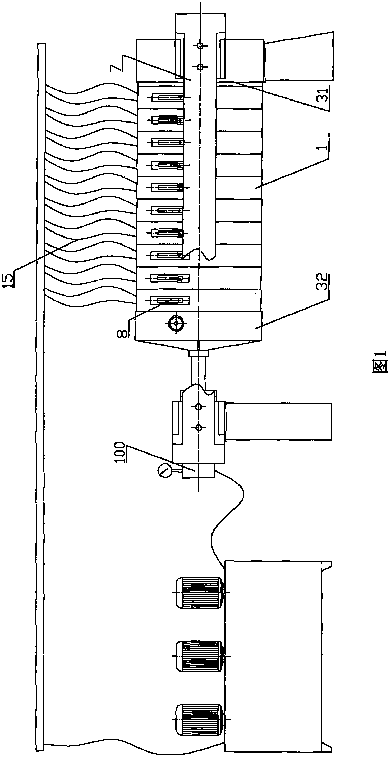
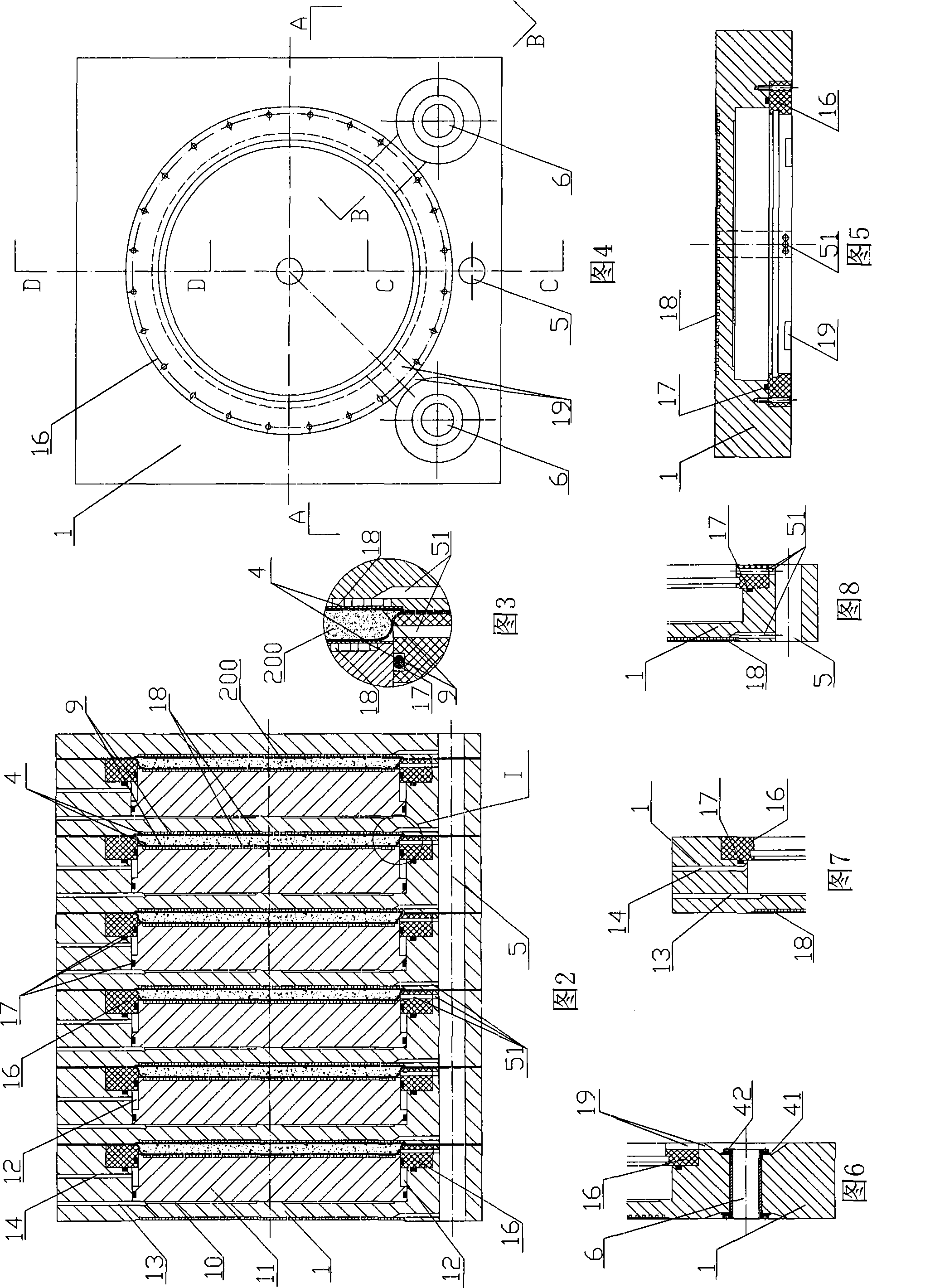
[0017] Refer to accompanying drawings 1-8. The present invention includes several plates 1 arranged in parallel and capable of moving back and forth relative to each other along the arrangement direction, and the dehydrator is provided with a hydraulic pressing mechanism for pressing the plates. Referring to accompanying drawing 1, in this embodiment, the hydraulic pressing mechanism for pressing the plate is a fixed plate 31 at one end of the plate arrangement and a pressing plate 32 acted by a hydraulic cylinder 100 at the other end of the plate arrangement. In this embodiment, a supporting slide rail 7 for a plate that can move back and forth relatively is provided beside the plate, and the plate that can move relatively forward and backward is provided with hanging ears 8 supported on the slide rail 7 . Foldable pull rods are connected between the plates that can move relatively forward and backward, and the pull rods are not shown in the accompanying drawings. In this wa...
Embodiment 2
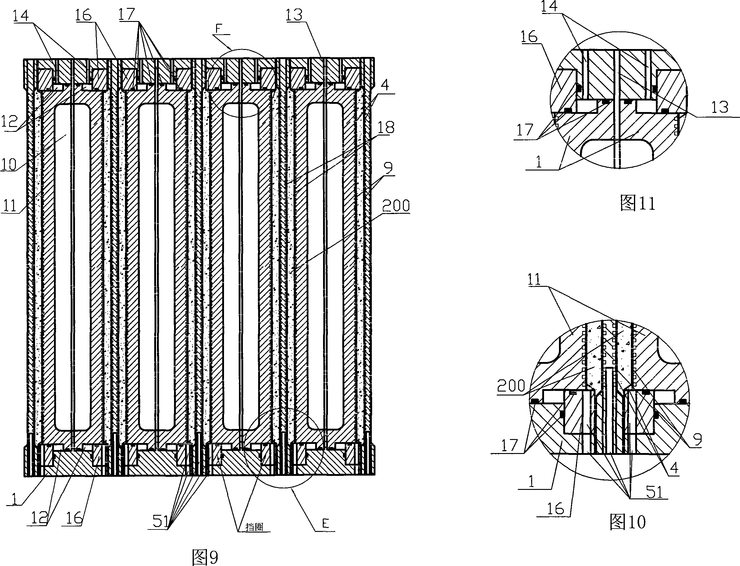
[0029] Refer to accompanying drawings 9-11. In this embodiment, squeeze boards 11 are arranged on both sides of the plate 1, and a board 20 without a hydraulic oil chamber and a squeeze board is arranged between the boards 1 that are provided with squeeze boards 11 on both sides. The adjacent plate portion is a part of the body of the adjacent plate 20 . The outer surface of the press plate is provided with a diversion groove 18 communicating with the outflow channel, and the surface of the adjacent plate facing the press plate is also provided with a diversion groove 18 communicated with the outflow channel. The plate 20 is also provided with a filtrate outflow main pipe, a sludge conveying main pipe, a communication hole 51 and a mud inlet tank.
[0030] The hydraulic oil chamber 10 is surrounded by the pressing plates 11 on both sides of the plate and the plate body. In the accompanying drawings, reference numeral 13 is the oil inlet and outlet holes of the oil chamber 10 ...
Embodiment 3
[0033] Refer to accompanying drawing 12. In this embodiment, on the basis of Embodiment 1, a sludge check valve 301 is provided in the upstream pipeline 300 of the sludge conveying channel, and a bypass 302 is also provided in the upstream pipeline after the check valve 301. Solenoid valve 303 is set on it, and for the plate 1a with sludge conveying main pipe at the last stage, its sludge conveying main pipe is also connected to air path 304, and solenoid valve 305 is set on air path 304. When the sludge is transported to each dehydration zone, the sludge feeding is stopped, and the sludge backflow is blocked by the check valve 301; after the pressing is completed, the solenoid valves 303 and 304 are opened at the same time, and the high-pressure gas is pressed into the sludge conveying dry from the air circuit 304. Pipe, the unpressed wet sludge in the dry pipe is pressed back to the sludge pool from the pipe 302.
PUM
 Abstract
Description
Claims
Application Information