Method for optimizing pneumatic connecting line or yarn and corresponding equipment

A technology for connecting equipment and connecting lines, which is applied to spinning machines, jointing devices, transportation and packaging, etc., and can solve the problems of heavy adjustment or replacement

Inactive Publication Date: 2008-04-23
MEDSAN SPA
View PDF0 Cites 19 Cited by
  • Summary
  • Abstract
  • Description
  • Claims
  • Application Information

AI Technical Summary

Problems solved by technology

The presence of a large number of work stations makes it particularly cumbersome to intervene on the individual coupling devices for adjustment or replacement

Method used


Image

  • Method for optimizing pneumatic connecting line or yarn and corresponding equipment
  • Method for optimizing pneumatic connecting line or yarn and corresponding equipment
  • Method for optimizing pneumatic connecting line or yarn and corresponding equipment

Examples


Embodiment Construction

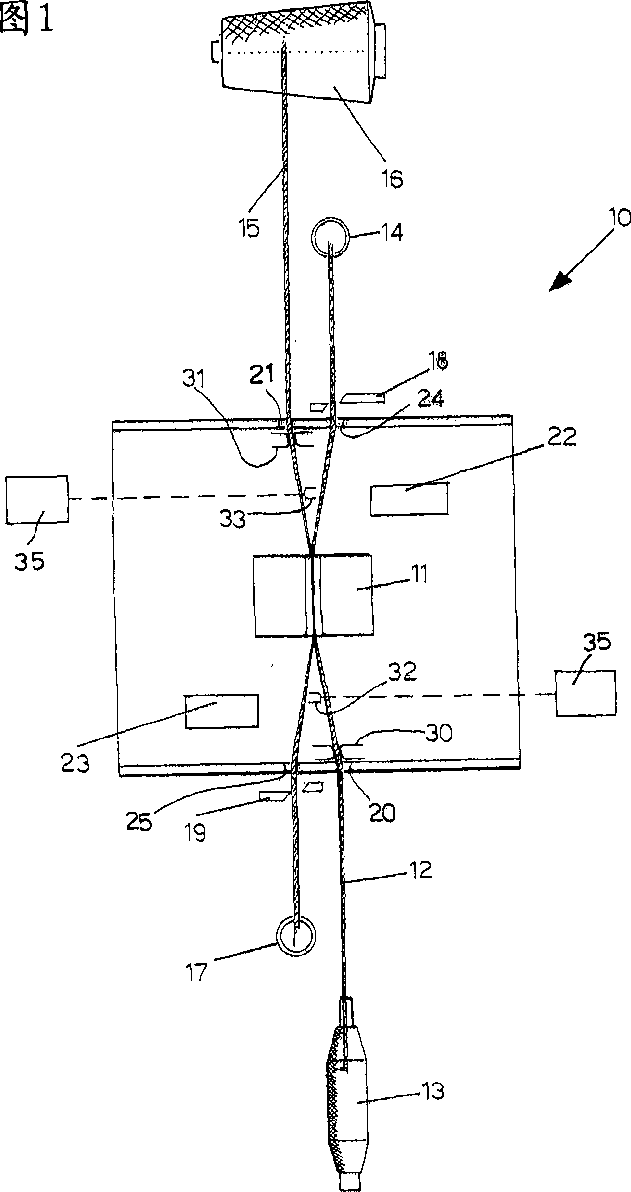
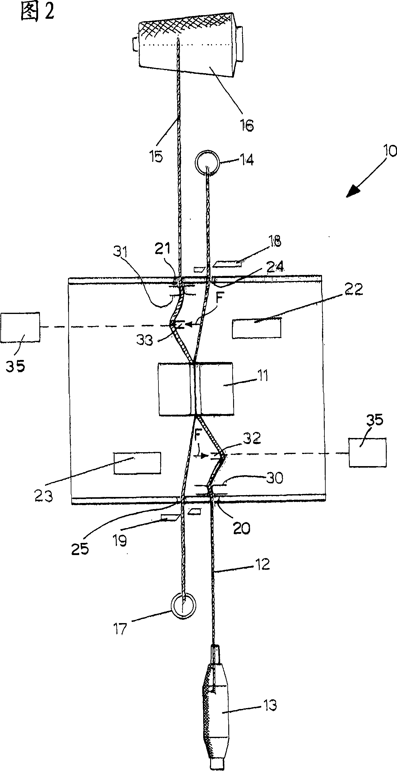
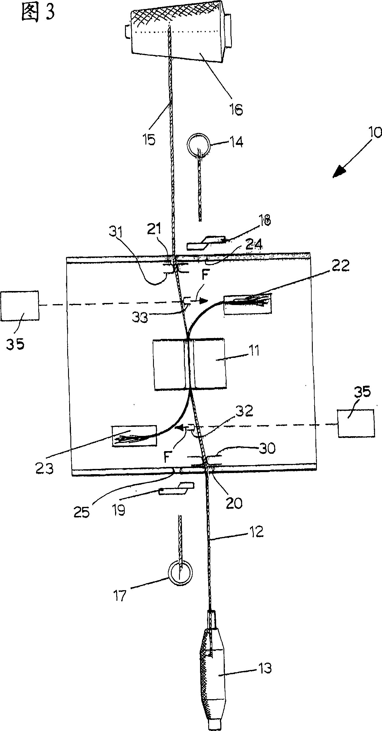
[0019] With reference to these figures, as an example, a device 10 for pneumatically joining threads or yarns is schematically shown for carrying out the method object of the invention for optimizing pneumatically joining threads or yarns.

[0020] In particular, the device 10 has a coupling chamber 11 inside which multiple streams of compressed air can be supplied through suitable nozzles not shown. Furthermore, the coupling chamber 11 is provided with a cover, which is also not shown. As shown in FIG. 1 , the first wire 12 from the bobbin 13 is introduced into the device 10 through the guide sleeve 20 , passed through the coupling cavity 11 , and inserted into the second guide sleeve 24 until the first wire 12 passes through, for example, the first suction nozzle 14 is held in place on the opposite side of the coupling cavity 11.

[0021] Vice versa, the second wire 15 from the reel 16 is introduced into the device 10 through the guide sleeve 21, through the coupling cavity...


PUM


Abstract

A method for optimizing pneumatic connecting line or yarn includes the following steps: lines (12, 15)needed connecting are led into connecting cavity (11) of pneumatic connecting device (10); the lines (12, 15) entering into device (10) are locked; the ends of the lines (12, 15) are cut off; the ends of the lines (12, 15) are untwisted; the lines (12, 15) are dragged on the direction of connecting cavity (11) and cut off, the ends of the lines are open; the connecting is executed by compressing air, wherein, at least one step capable of adjusting measurement to intercept lines (12, 15) by at least two intercepting lever (32, 33) executes on the downstream of leading-points (20, 21) between the leading step and the untwisting step to extend the path of the lines (12, 15) and change the length of the ends of the lines (12, 15) outspread. The invention also relates to a device for executing the method.

Description

technical field [0001] The present invention relates to a method and associated apparatus for optimizing pneumatically joined threads or yarns. [0002] Compressed air spinning yarn joining equipment known as an air joiner uses compressed air as a device for untwisting the ends of the threads to be joined and as a device for joining the threads by interlacing fibers. [0003] Such equipment includes: a guide bush, which facilitates the correct insertion of the wires to be joined into the adapter; a clamp, which locks the wires to be joined; scissors, which cuts off the ends of said wires; and a spout, which is deployed by means of compressed air to be severed the ends; the adjusting rod, which pulls out the untied ends, overlapping said ends for joining; and the splicing chamber, which is provided with longitudinal slots for guiding the ends of the threads or yarns to be joined and for jet compression Side holes or spouts for air. A cover may also be provided to close the lo...

Claims


Application Information

Patent Timeline
Patent Type & Authority Applications(China)
IPC IPC(8): D01H15/00D01H4/48
CPCB65H2701/31B65H69/063D01H15/00B65H69/061
Inventor M·普雷米
Owner MEDSAN SPA
Why Eureka
Try Eureka