Processing method for wafer

A processing method and wafer technology, applied in the direction of stone processing equipment, fine working devices, manufacturing tools, etc., can solve the problems of low processing efficiency, troublesome, and the pre-cutting method does not mention any relevant content, etc. Efficiency, efficient processing effect

Active Publication Date: 2008-04-23
DISCO CORP
View PDF1 Cites 4 Cited by
  • Summary
  • Abstract
  • Description
  • Claims
  • Application Information

AI Technical Summary

Benefits of technology

This patented technology allows for efficient use of wafers by replacing worn or damaged ones while maintaining their sharpness after being severed from them. It also ensures accurate alignment between different parts of the wafer before further treatment steps are done.

Problems solved by technology

This patented technical problem addressed in this patents relates to improving the efficient division of semiconductor substrate during manufacturing processes involving chip separation between different tools involved in the fabrication process. Current solutions involve removing unnecessary parts beforehand without ensuring accurate positioning accuracy due to damage caused by handling small defects near certain areas on each side of the cutting edge. Additionally, current solution requires replacement of worn cutting tools every time, leading to decreased productivity.

Method used


Image

  • Processing method for wafer
  • Processing method for wafer
  • Processing method for wafer

Examples


Embodiment Construction

[0027] Hereinafter, a wafer processing method as the best mode for carrying out the present invention will be described with reference to the drawings.

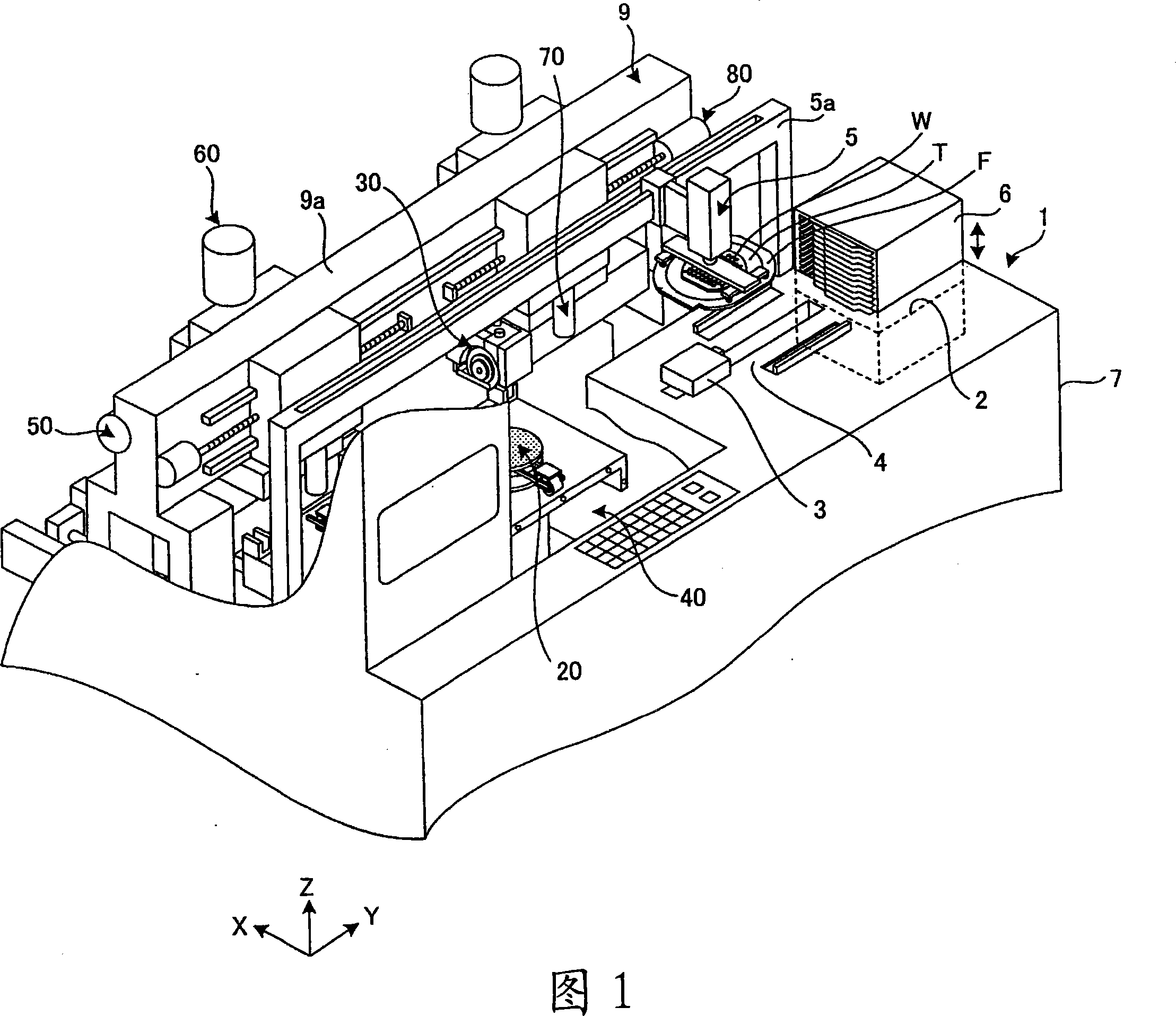
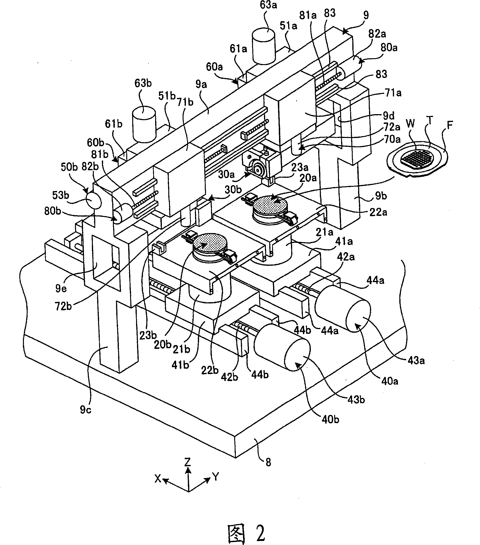
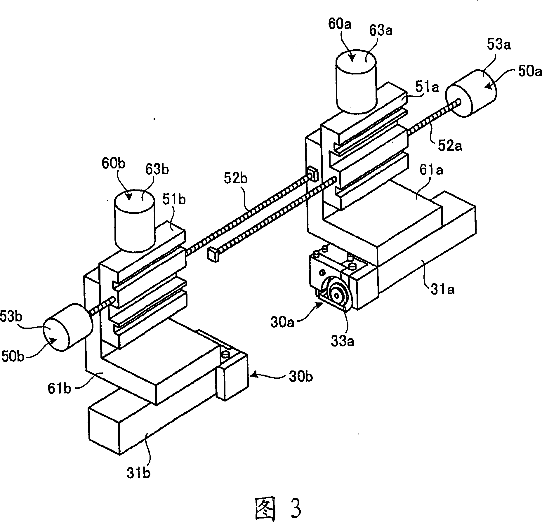
[0028] 1 is a cutaway perspective view showing a part of the cutting device used in order to implement the wafer processing method of this embodiment; FIG. 2 is a perspective view showing the main part of the cutting device shown in FIG. 1; A perspective view of a structural example; FIG. 4 is a side view showing a structural example around the cutting unit.

[0029] The cutting device 1 according to the present embodiment cuts the wafer W along the planned dividing line. As a schematic structure, as shown in FIG. 1 , it has: a wafer cassette table 2; and also has: suction cup table 20; cutting unit 30; machining feed unit 40; index feed unit 50; depth of cut feed unit 60; alignment unit 70;

[0030]The wafer cassette workbench 2 is a workbench that can be freely raised and lowered along the Z axis, and is arranged at one en...


PUM


Abstract

A method for processing a wafer is provided in the present invention, even during halfway of cutting the wafer when the broken cutting tool is changed into new cutting tool, need to processing pre-cutting treatment, not need to discharge the wafer in the halfway, and not need to process alignment again, can highly-effective process the wafer. During the cutting halfway of wafer (W) of cutting working procedure, when changing the cutting tool into new cutting tool (33b'), leading the wafer in the cutting halfway to maintain holding on a suction cup work bench (20a), leading the false wafer (DW) to maintain on one suction cup work bench (20b) without holding the cutting halfway wafer (W), using with a cutting unit (30b) mounted with new cutting tool (33b') to execute pre-cutting for cutting the false wafer (DW).

Description


Claims


Application Information

Patent Timeline
Owner DISCO CORP
Why Eureka
Try Eureka