Manipulator system

A manipulator and actuator technology, applied in the field of manipulator systems, can solve problems such as inability to understand the usage and inconvenience

Active Publication Date: 2008-04-30
KARL STORZ GMBH & CO KG
View PDF3 Cites 37 Cited by
  • Summary
  • Abstract
  • Description
  • Claims
  • Application Information

AI Technical Summary

Problems solved by technology

However, there are cases where a plurality of control units are prepared for connection, and if the usage history information of the operation unit is saved in a predetermined control unit in advance, the operation unit will be connected to other control units, and the usage status cannot be known. very inconvenient

Method used


Image

  • Manipulator system
  • Manipulator system
  • Manipulator system

Examples


Embodiment Construction

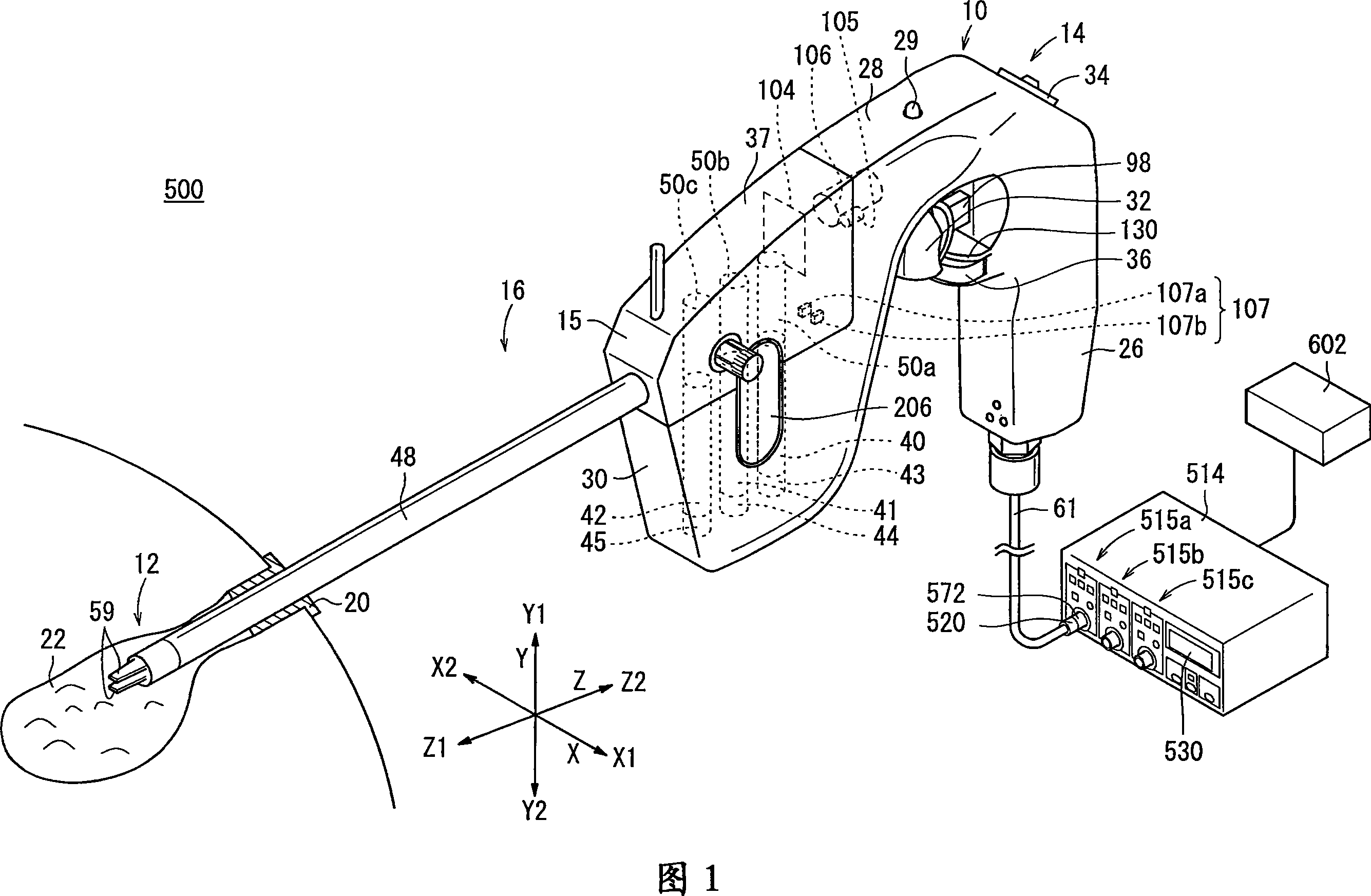
[0047] A medical manipulator system 500 as an embodiment of the present invention will be described below with reference to FIGS. 1 to 20 . The manipulator system 500 (see FIG. 1 ) is used for laparoscopic surgery and the like.

[0048] As shown in FIG. 1 , the manipulator system 500 has a manipulator 10 and a controller 514 .

[0049] A detachable connector 520 is provided at the connection portion between the manipulator 10 and the controller 514 .

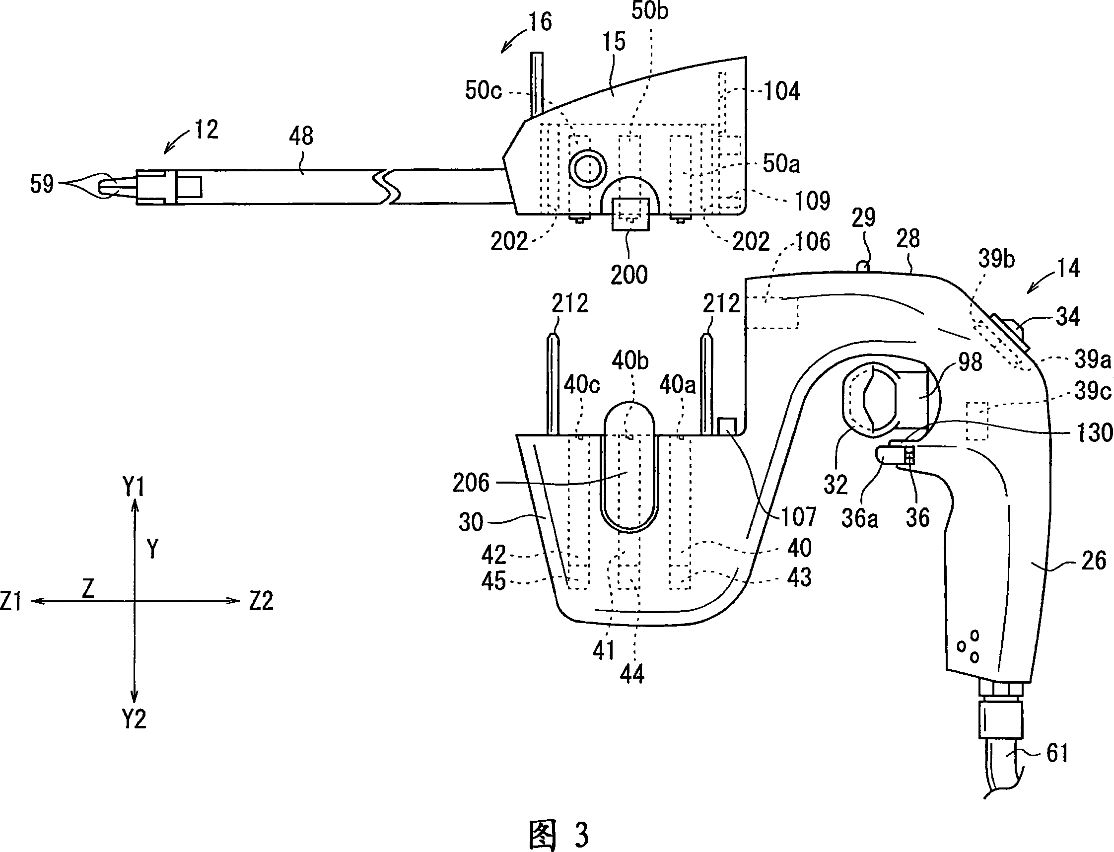
[0050]The manipulator 10 is used to perform predetermined treatments such as grasping a part of a living body or bending a needle by the distal operating part 12 . The basic configuration of the manipulator 10 includes an operation unit 14 and a working unit 16 . The controller 514 electrically controls the manipulator 10 , and the controller 514 is connected to the cable 61 extending from the lower end of the grip handle 26 through the connector 520 .

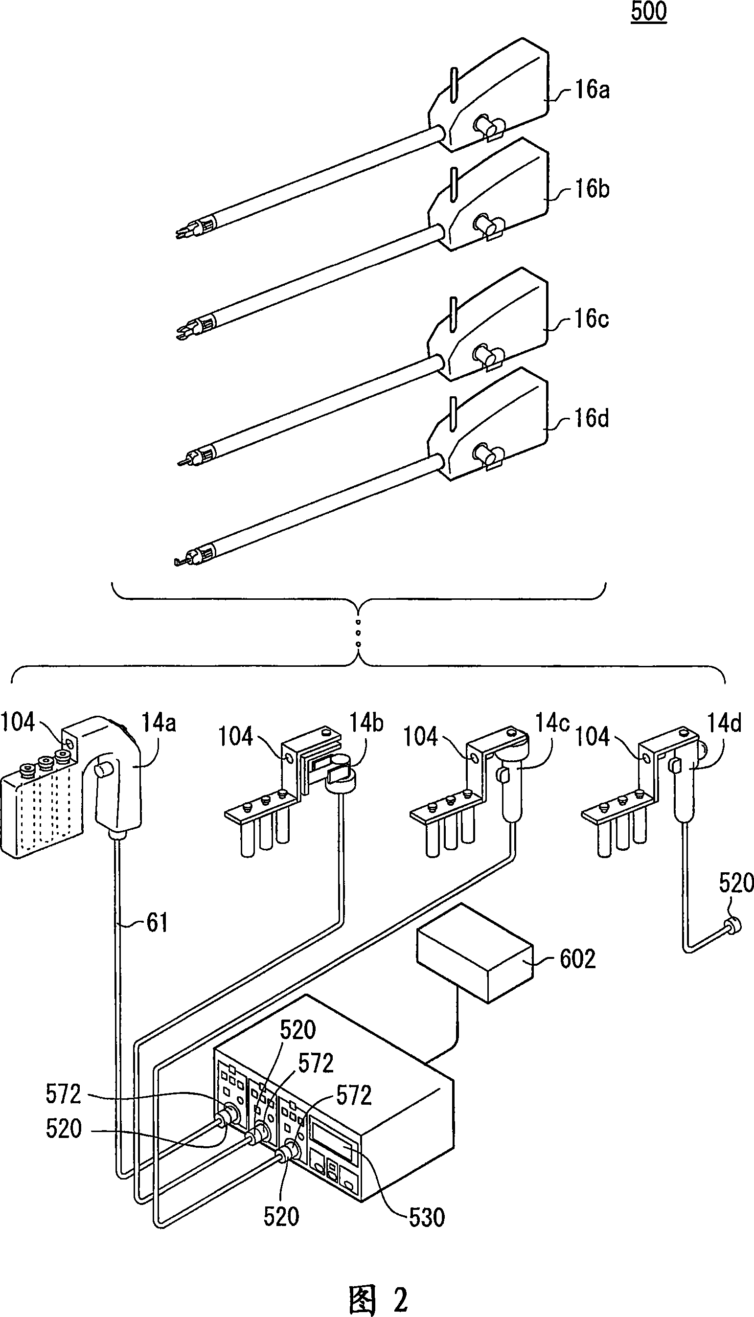
[0051] The controller 514 can independently and simultaneously control t...


PUM


Abstract

This invention provide a manipulator system. A manipulator (10) comprises an actuator block (30) and a working unit (16) attachable to and detachable from the actuator block (30). The actuator block (30) has a motor (40, 41, 42), the working unit (16) has a connecting shaft (48) and an end working portion (12) disposed at the distal end thereof, and the end working portion (12) is rotated in conjunction with the motor (40, 41, 42). The working unit (16) further has a two-dimensional code (104) holding an identification signal, and the actuator block (30) further has an infrared camera (106) for recognizing the identification signal in the code (104) and supplying it to a controller (514), is the camera (106) being not in contact with the code (104). The controller (514) controls the working unit (16) based on the supplied identification signal.

Description

technical field [0001] The present invention relates to a manipulator and a manipulator system for controlling the manipulator, in particular to a manipulator system having a manipulator composed of an actuator part and a working part, wherein the actuator part has an actuator, and the working part has a The actuator unit is detachably attachable to the actuator unit and operates in cooperation with the actuator. Background technique [0002] In laparoscopic surgery, several small holes are made in the abdomen of the patient, an endoscope, a manipulator (or forceps), etc. are inserted, and the operator performs the operation while viewing the image of the endoscope on a monitor. Since such laparoscopic surgery does not require a laparotomy, the burden on the patient is small, and the number of recovery days and hospitalization days after surgery can be significantly shortened, so the scope of application is expected to be expanded. [0003] For example, as described in Japa...

Claims


Application Information

Patent Timeline
Patent Type & Authority Applications(China)
IPC IPC(8): A61B17/00A61B17/94A61B1/00A61B19/00
CPCA61B19/44A61B2017/00482A61B2017/0046A61B2019/442A61B2019/2242A61B2017/00398A61B2019/2249A61B19/5212A61B2019/448A61B19/22A61B2019/4826A61B19/5225A61B2019/4815A61B2019/521A61B90/96A61B2090/0805A61B34/70A61B34/71A61B2090/309A61B90/361A61B34/72A61B90/90A61B90/98A61B2090/0803A61B90/37
Inventor 大森繁佐野弘明一柳正雄神野诚
Owner KARL STORZ GMBH & CO KG
Why Eureka
Try Eureka