System and method for interfacing multi-agent system

a multi-agent and agent technology, applied in the field of computerized control systems, can solve the problems of complex messages and agents' functions, difficult to determine the improvement or adjustment of the system operation, and difficulty in monitoring the operation of multi-agent distributed control systems

Inactive Publication Date: 2007-06-05
ROCKWELL AUTOMATION TECH
View PDF13 Cites 82 Cited by
  • Summary
  • Abstract
  • Description
  • Claims
  • Application Information

AI Technical Summary

Benefits of technology

[0009]In particular, the present invention relates to a system for allowing a user to interact with a multi-agent distributed control system. The system includes a computerized terminal on which is displayed a user interface, where the user interface includes a first window displaying a workflow among a first plurality of agents of the multi-agent system.
[0010]The present invention also relates to a distributed control system that includes a network, a plurality of controllers programmed with a plurality of agents, wherein the controllers are in communication with one another by way of the network, and a terminal coupled to the network and capable of providing a human machine interface (HMI). The HMI displays a plurality of windows on which are displayed information regarding at least some of the agents, a plurality of messages communicated among at least some of the agents, and a workflow occurring among at lea

Problems solved by technology

Although multi-agent distributed control systems offer many advantages, multi-agent distributed control systems are difficult to monitor while in operation.
This is due at least in part to the variation in agents and their responsibilities within such control systems, the large numbers of messages that are typically sent among the agents of such systems, and the complexity of both the messages and the agents' functions.
Further, in part because of the difficulty in monitor

Method used


Image

  • System and method for interfacing multi-agent system
  • System and method for interfacing multi-agent system
  • System and method for interfacing multi-agent system

Examples


Embodiment Construction

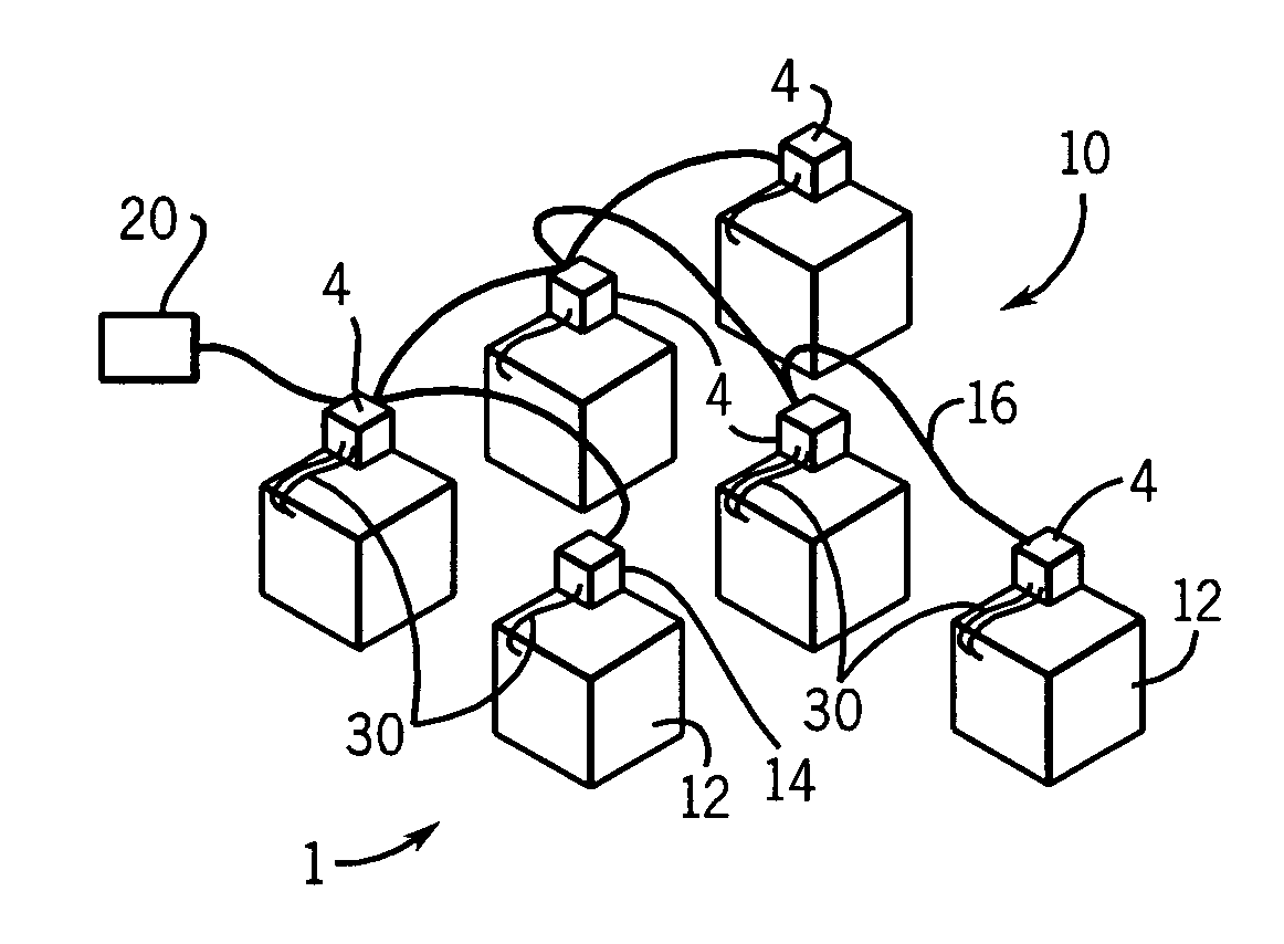
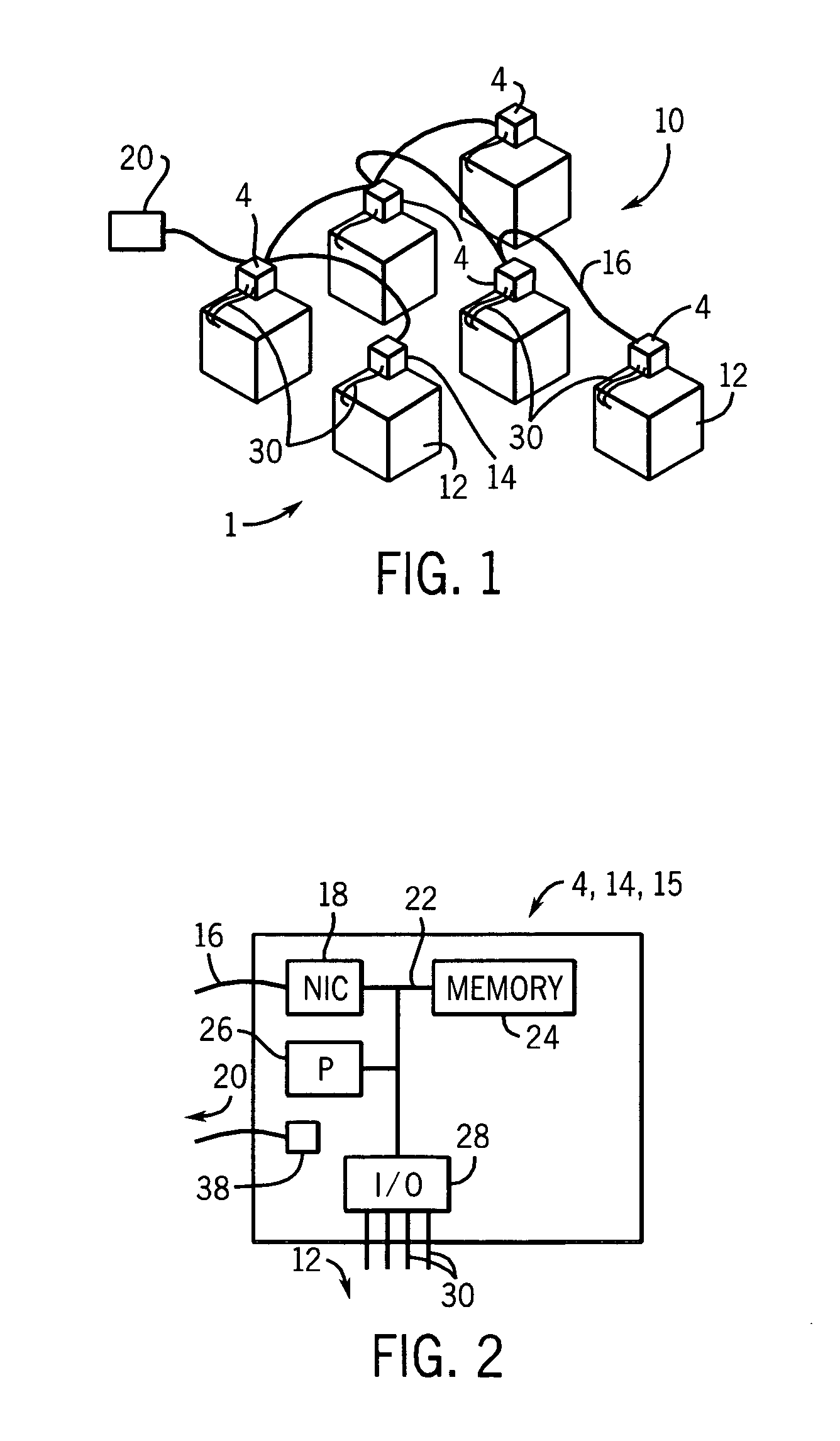
[0018]Referring to FIG. 1, a distributed control system 10 controls and / or monitors the operation of a process performed by a plurality of machines 12, each of which is associated with a respective electronic computer or controller 4,14 of the control system. Each controller 4,14 is configured for electrical communication through a respective I / O line 30 with its respective machine or machines. The process can be any of a variety of different processes in a variety of environments such as, for example, an industrial process performed by a plurality of manufacturing machines such as drills, lathes, ovens, mills and the like. Also, for example, the process could relate to the distribution of a resource or multiple resources, such as water within a naval vessel, energy from energy producers to energy consumers by way of a power distribution grid, or heated or cooled air within a building employing a heating, ventilation and air-conditioning (HVAC) system. In such embodiments, the contr...


PUM


Abstract

A system and method of interacting with a multi-agent distributed control system employing a plurality of controllers on which are programmed a plurality of agents in which the controllers are coupled by a network are disclosed. The method includes providing a computer program capable of operating a user interface, where the computer program is in communication with the agents via the network. The method further includes displaying agent-related information on the user interface by way of a plurality of windows, where within a first of the windows is further displayed a workflow among at least some of the agents, and within a second of the windows is further displayed at least one of a plurality of messages communicated among at least some of the agents, a work unit requested by at least one of the agents, and message content associated with at least one of the messages.

Description

CROSS-REFERENCE TO RELATED APPLICATIONS[0001]This application is based on U.S. provisional patent application no. 60 / 553,360 filed Mar. 15, 2004 and entitled “Agent Program Environment”, and also is a continuation-in-part of U.S. patent application Ser. No. 10 / 737,384 filed on Dec. 16, 2003 and entitled “Decentralized Autonomous Control for Complex Fluid Distribution Systems”, which is based on provisional application No. 60 / 433,892 filed Dec. 16, 2002 and entitled “Agent-Based Active Diagnostics System for Complex Distribution Networks”, each of which is hereby incorporated by reference herein, and claims the benefit thereof.BACKGROUND OF THE INVENTION[0002]The present invention relates to computerized control systems and, more particularly, distributed control systems that employ multiple, distinct control devices that are connected to one another by way of a network and that interact with one another in a manner allowing for overall control of a process.[0003]A variety of commerc...

Claims


Application Information

Patent Timeline
IPC IPC(8): G05B15/00G05B19/18G05B9/02G06F19/00G06E1/00G06F17/00G05B19/418G06F11/32G06F11/36G06Q10/00
CPCG05B19/41875G06Q10/04G05B2219/33304Y02P90/02
Inventor TICHY PAVELMATURANA FRANCISCO P.HALL KENWOOD H.STARON RAYMOND J.HACEK OVER SLECHTA PETRMA HACEK OVER RIK VLADIMIR
Owner ROCKWELL AUTOMATION TECH
Why Eureka
Try Eureka