
Device and method for controlling robot

a robot and control device technology, applied in the field of robot control devices, can solve the problems of not reasonable, difficult to realize the feeding/taking out tasks of several workpieces subjected to different processing particulars (i.e., different production cycles) together in one series of operation programs, and achieve the effect of reducing the waiting time of the robo

Active Publication Date: 2006-12-07
FANUC LTD
View PDF17 Cites 65 Cited by
  • Summary
  • Abstract
  • Description
  • Claims
  • Application Information

AI Technical Summary

Benefits of technology

[0011] It is an object of the present invention to provide device and method, for controlling a robot, which can solve the above-described several problems in a manufacturing system using a robot.
[0012] It is another object of the present invention to provide a robot controller or a robot control method, capable of making a single robot efficiently perform tasks relating to a plurality of workpieces in a parallel or synchronous manner, while comprehending the operating state of the manufacturing system as occasion demands.
[0013] It is a further object of the present invention to provide a robot controller or a robot control method, capable of restarting a task of a robot surely and safely, regardless of the operator's understanding of a manufacturing system, when the manufacturing system stops due to an emergency.

Problems solved by technology

Usually, it is not reasonable, during a period when one work unit is performed, to insert a different work unit therein.
In a manufacturing system for manufacturing a plurality of products in a parallel or synchronous manner, when, for example, a single robot operates to feed workpieces into, and take out workpieces from, a plurality of processing machines, it is generally difficult to realize feeding / taking-out tasks for several workpieces subjected to different processing particulars (i.e., different production cycles) together in one series of operation programs.
However, in this configuration, the robot performs a subsequent work unit only after completing one work unit, so that, in a case where time (e.g., a processing time) required to perform a common work unit is different for the respective workpieces, a cycle time of the feeding and taking-out tasks for workpieces relative to all processing machines is dominated by a workpiece involving a time-consuming work unit.
In other words, it is difficult, in this configuration, to effectively reduce the waiting time of the robot and thus to efficiently perform the tasks, while comprehending the operating state of the manufacturing system as occasion demands.
When the operator manually intervenes in the operation of the manufacturing system, the state of the manufacturing system alters from the state at the instant of the emergency stop and thus loses a correlation with the operation program of the robot, so that the task cannot be restarted as it is.

Method used


Image

  • Device and method for controlling robot
  • Device and method for controlling robot
  • Device and method for controlling robot

Examples


Embodiment Construction

[0037] The embodiments of the present invention are described below, in detail, with reference to the accompanying drawings. In the drawings, the same or similar components are denoted by common reference numerals.

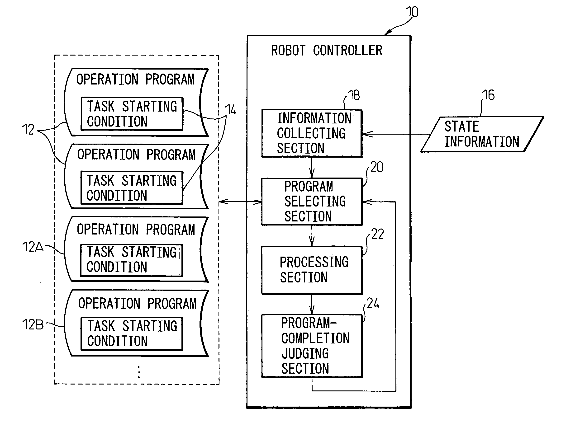
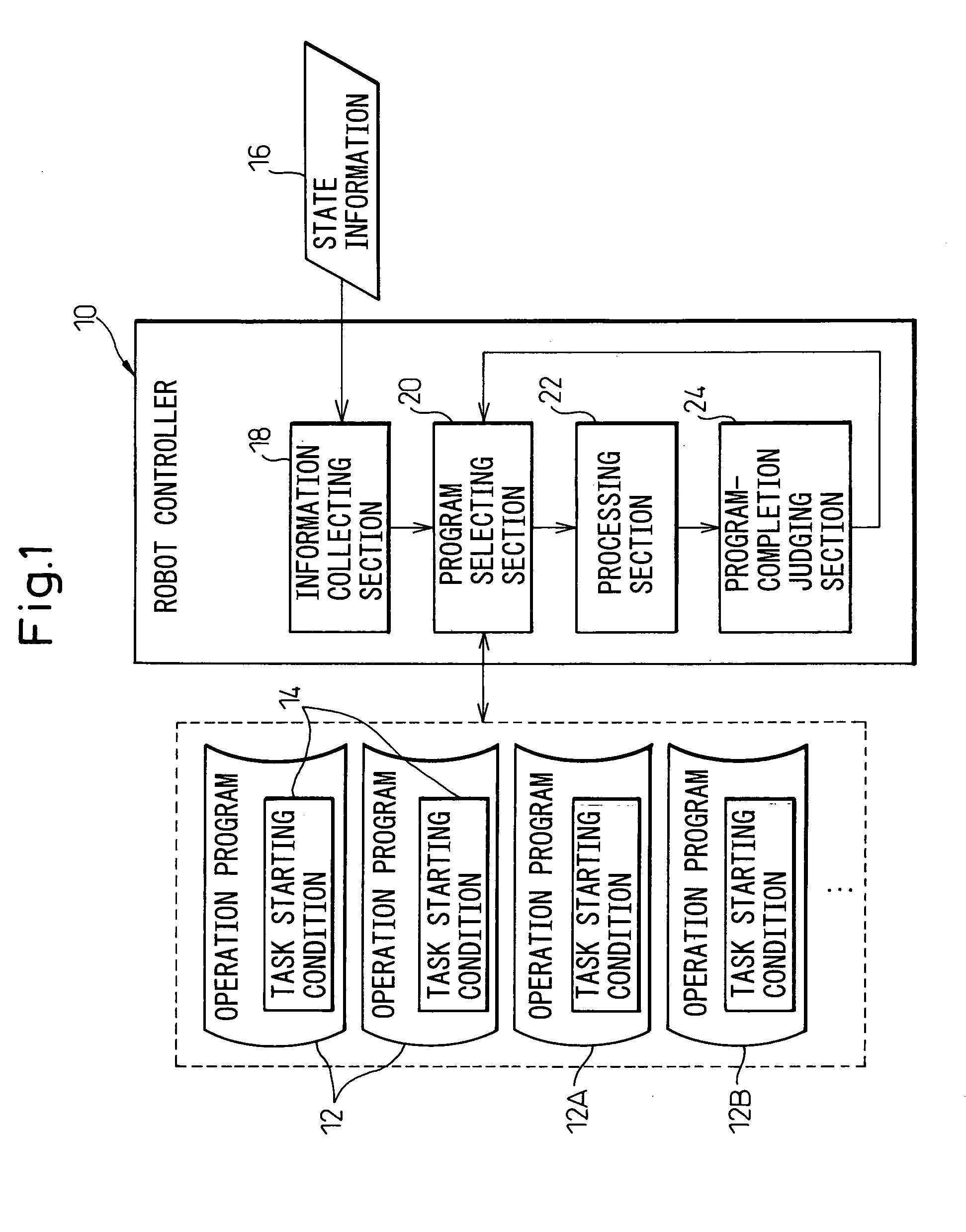
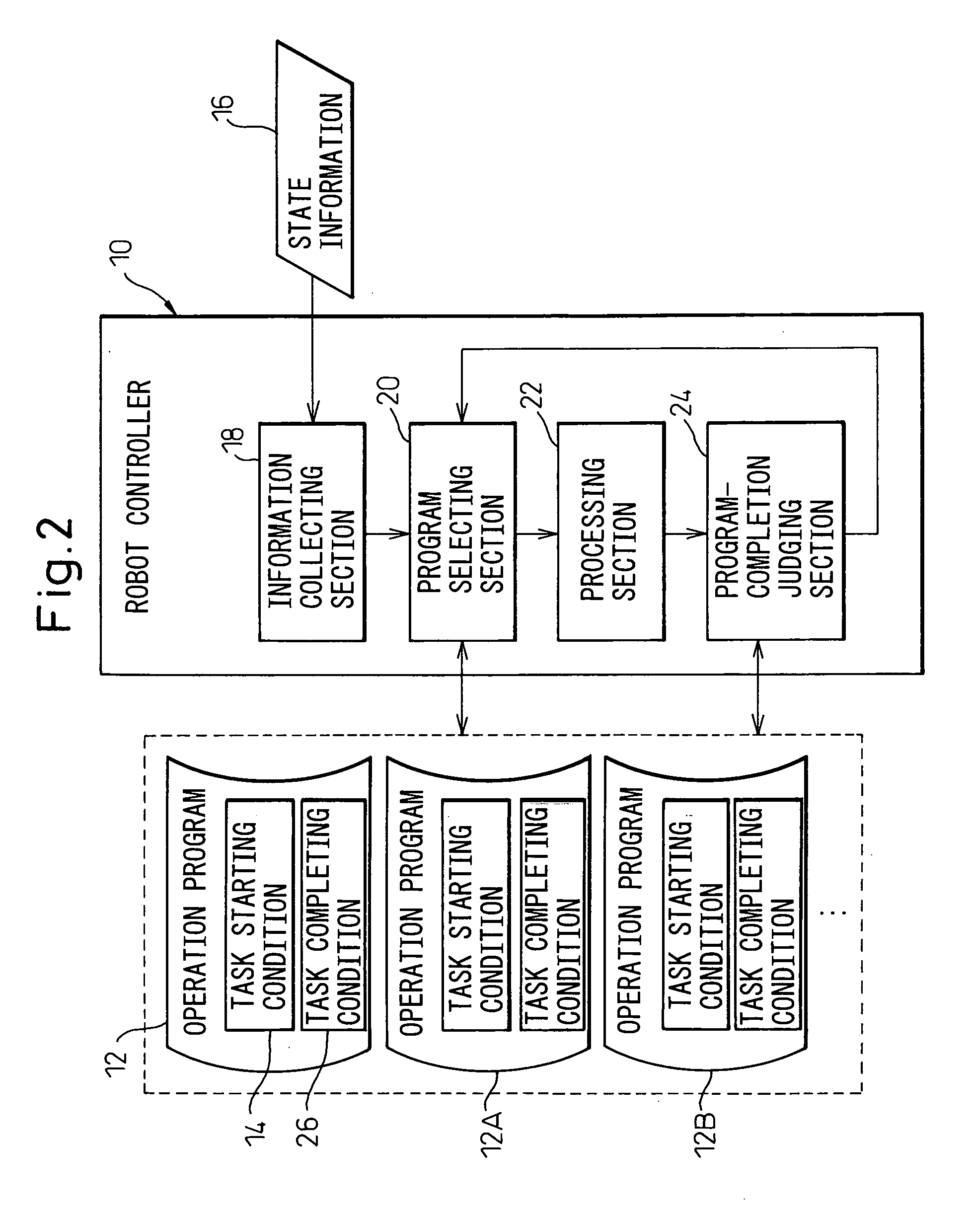
[0038] Referring to the drawings, FIG. 1 shows in a functional block diagram a basic configuration of a robot controller (or a device for controlling a robot) 10 according to the present invention. The robot controller 10 is configured to make a robot execute tasks including a plurality of work units in a parallel or synchronous manner for several workpieces, in accordance with a plurality of operation programs 12 for individually commanding the plurality of work units. Each of the plurality of operation programs 12 includes a description of a task starting condition 14 as a precondition for starting a corresponding work unit by the robot. The robot controller 10 includes an information collecting section 18 collecting state information 16 showing, in real time, a state o...


PUM


Abstract

A robot controller making a robot execute tasks including several work units in a parallel manner for several workpieces, in accordance with several operation programs for individually commanding the work units. The robot controller includes an information collecting section collecting state information showing, in real time, a state of an environment of the robot; a program selecting section selecting a first executable program satisfying a task starting condition, from operation programs ready to be executed for workpieces, based on the state information; a processing section processing, for execution, the first executable program; and a program-completion judging section judging whether the processing section has completed a processing of the first executable program. The program selecting section selects, based on the state information, a second executable program satisfying the task starting condition, from the operation programs ready to be executed, so as to satisfy a judgment of the program-completion judging section.

Description

BACKGROUND OF THE INVENTION [0001] 1. Field of the Invention [0002] The present invention relates to a device for controlling a robot. The present invention also relates to a method for controlling a robot. [0003] 2. Description of the Related Art [0004] An industrial robot (hereinafter referred to simply as a robot) operates so as to follow a certain operation program (or a task program). When several kinds of operation programs are prepared, which correspond to the types of tools (or end effecters) attached to the robot, the types of objective workpieces, the contents of tasks, etc., and are suitably and selectively given to a robot, the robot as a single machine can execute various kinds of tasks. In order to prepare an operation program to control the operation of a robot, an operator makes the respective control axes of the robot run in a manual mode at low speed, generally by using an operating panel or “a teach pendant”, so as to sequentially position a tool at a plurality of...

Claims


Application Information

Patent Timeline
IPC IPC(8): G06F19/00B25J9/16G05B19/4067G05B19/4155
CPCB25J9/1656G05B2219/40584B25J9/1679
Inventor NIHEI, RYOKATO, TETSUAKINISHI, HIROJI
Owner FANUC LTD
Learn More