Medical manipulator

Active Publication Date: 2006-02-07
TERUMO KK
View PDF6 Cites 66 Cited by
  • Summary
  • Abstract
  • Description
  • Claims
  • Application Information

AI Technical Summary

Benefits of technology

[0023]Since the control unit sets the first power transmission unit in the predetermined initial positional state after the normal completion of an operation, the medical manipulator can be used immediately after the connection of the same to the power source without requiring a troublesome return-to-origin operation. Thus, troublesome work in a tense situation of surgical operation can be avoided and thereby the efficiency of t

Problems solved by technology

The master-slave manipulator system is a complicated system including a controller for controlling the joints of the articulated arms, an electrical control system, and many parts including wiring lines.
Medical instruments, particularly, surgical instruments, as well as medical robots, cannot be used for surgical operations unless those instruments are sterilized and cleaned.
It is very troublesome to operate a medical robot for initialization for returning the medical robot to its initial positional state during a surgical operation.
Therefore, it is the most important pr

Method used


Image

  • Medical manipulator
  • Medical manipulator
  • Medical manipulator

Examples


first embodiment

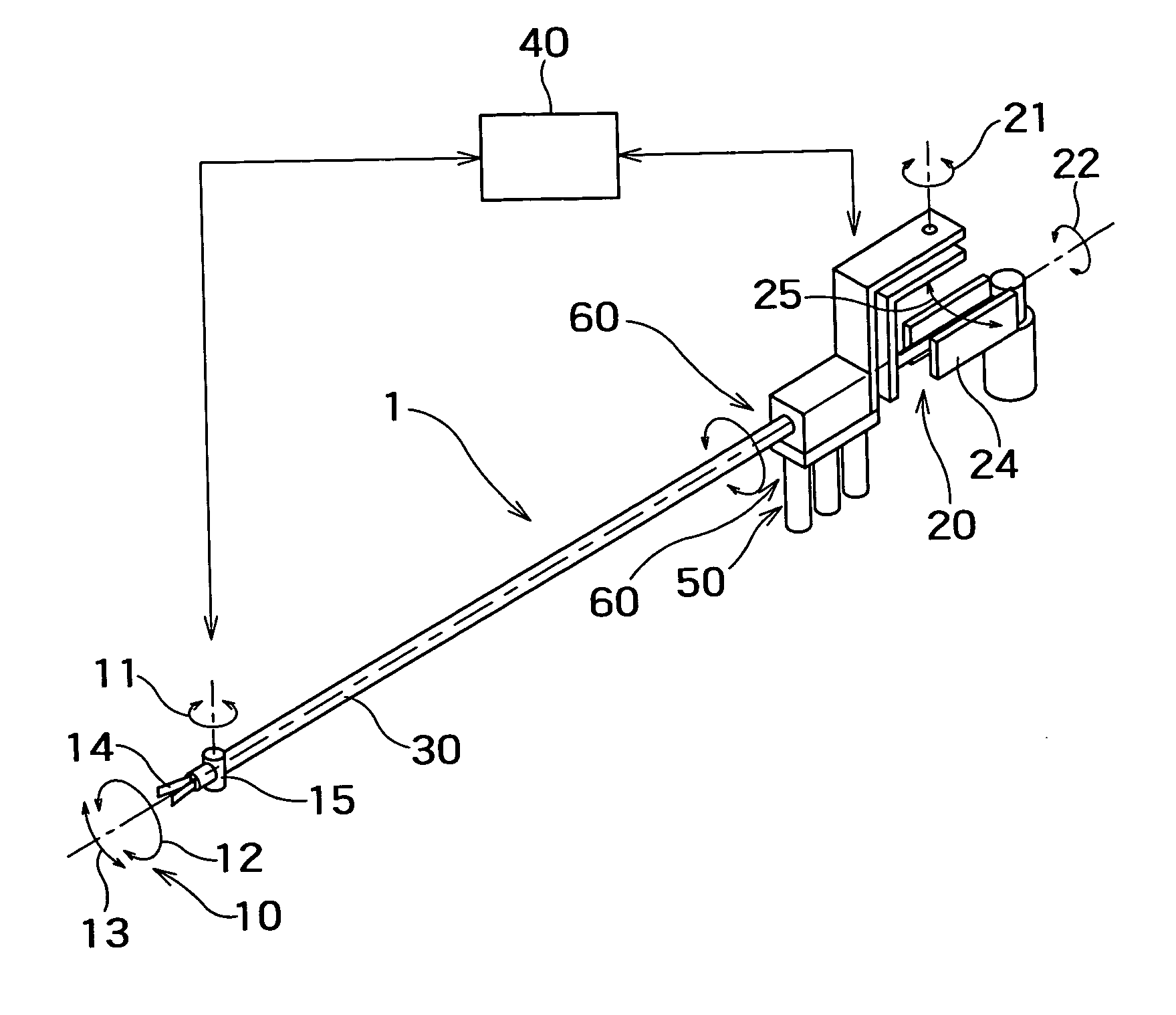
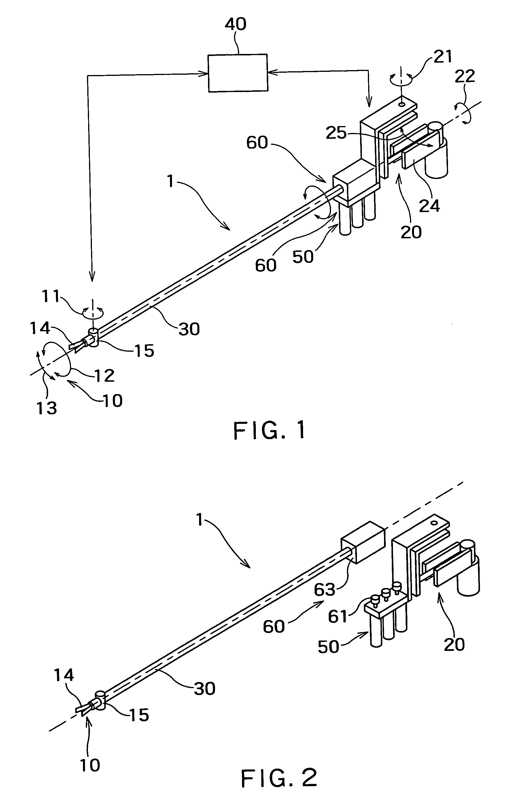
[0041]Referring to FIG. 1, a medical manipulator 1 in a first embodiment according to the present invention comprises a working unit 10 that performs necessary operations, an operating unit 20 for generating instructions specifying operations to be performed by the working unit 10, a drive unit 50 for driving the working unit 10 on the basis of instructions generated by the operating unit 20, a power transmission mechanism 60 for transmitting the drive force of the drive unit 50 to the working unit 10, and a control unit 40 for controlling the power transmission mechanism 50 to make the working unit 10 operate on the basis of instructions generated by the operating unit 20. The working unit 10 and the operating unit 20 are connected by a bar-shaped connecting unit 30. The working unit 10 is disposed at one end of the connecting unit 30, and the operating unit 20 and the drive unit 50 are disposed near the other end of the connecting unit 30. The drive unit 50 includes three motors. ...

second embodiment

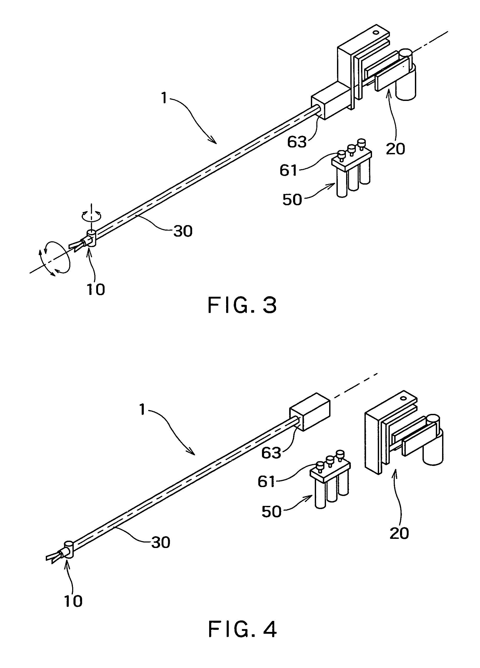
[0052]A medical manipulator 1 in a second embodiment according to the present invention will be described with reference to FIGS. 5, 6, 10 and 11. The medical manipulator 1 has a first power transmission unit 61 and a second power transmission unit 63. As shown in FIGS. 5 and 6, an initialization detector 70 can be combined with the first power transmission unit 61. The initialization detector 70 can freely be combined with and separated from the first power transmission unit 61 after the first power transmission unit 61 has been disconnected from the second power transmission unit 63. The initialization detector 70 is combined with the first power transmission unit 61 after disconnecting the first power transmission unit 61 from the second power transmission unit 63.

[0053]Referring to FIGS. 10 and 11, the initialization detector 70 is mounted on a base 76. The initialization detector 70 has couplings 70a supported on the base 76. The couplings 70a are engaged with the couplings of ...


PUM


Abstract

A medical manipulator comprises a working unit (10) that performs operations, an operating unit (20) that generates instructions, a drive unit (50) that drives the working unit on the basis of instructions given thereto by the operating unit, a power transmission mechanism (60) for transmitting driving force of the drive unit to the working unit, and a control unit (40) for controlling the power transmission mechanism on the basis of instructions given thereto by the operating unit. The power transmission mechanism includes a first power transmission unit (61) interlocked with the drive unit, and a second power transmission unit (63) interlocked with the working unit and capable of being detachably connected to the first power transmission unit. A back drive torque of the first power transmission unit is larger than a back drive torque of the second power transmission unit.

Description

CROSS-REFERENCE TO RELATED APPLICATIONS[0001]This application is based upon and claims the benefit of priority from the prior Japanese Patent Application No. 2002-271947, filed on Sep. 18, 2002; the entire contents of which are incorporated herein by reference.BACKGROUND OF THE INVENTION[0002]1. Field of the Invention[0003]The present invention relates to a medical manipulator and, more particularly, to a medical manipulator having a simple mechanism and excellent in operability and safety.[0004]2. Description of the Related Art[0005]Referring to FIG. 13, laparoscopic cholecystectomy forms three small incisions 151, 152 and 153 in the abdominal wall, fits tracheal tubes 154 in the incisions 151, 152 and 153, inserts an endoscope 161, and forceps 171 and 172 through the tracheal tubes 154 into the abdomen. An operator 160, usually, a surgeon, conducts an operation, watching an image taken by the endoscope 161 and displayed on the screen of a monitor 162. Laparoscopic cholecystectomy ...

Claims


Application Information

Patent Timeline
IPC IPC(8): A61B17/32B25J1/00A61B17/00A61B19/00
CPCA61B17/00234A61B19/22A61B19/26A61B2019/2249A61B2017/00017A61B2017/00477A61B34/70A61B34/72A61B90/50
Inventor JINNO, MAKOTOSUNAOSHI, TAKAMITSU
Owner TERUMO KK
Why Eureka
Try Eureka