Thread-through device for sewing machine

一种穿线装置、缝纫机的技术,应用在上线装置、缝纫机元件、缝纫机用套圈机构等方向,能够解决作业效率降低等问题,达到提高识别性、穿线作业可靠、可靠识别缝线的效果

Active Publication Date: 2008-04-30
JUKI CORP
View PDF1 Cites 6 Cited by
  • Summary
  • Abstract
  • Description
  • Claims
  • Application Information

AI Technical Summary

Problems solved by technology

In addition, there is a problem that the control lever is operated many times uselessly, and the working efficiency is reduced.

Method used


Image

  • Thread-through device for sewing machine
  • Thread-through device for sewing machine
  • Thread-through device for sewing machine

Examples


Embodiment Construction

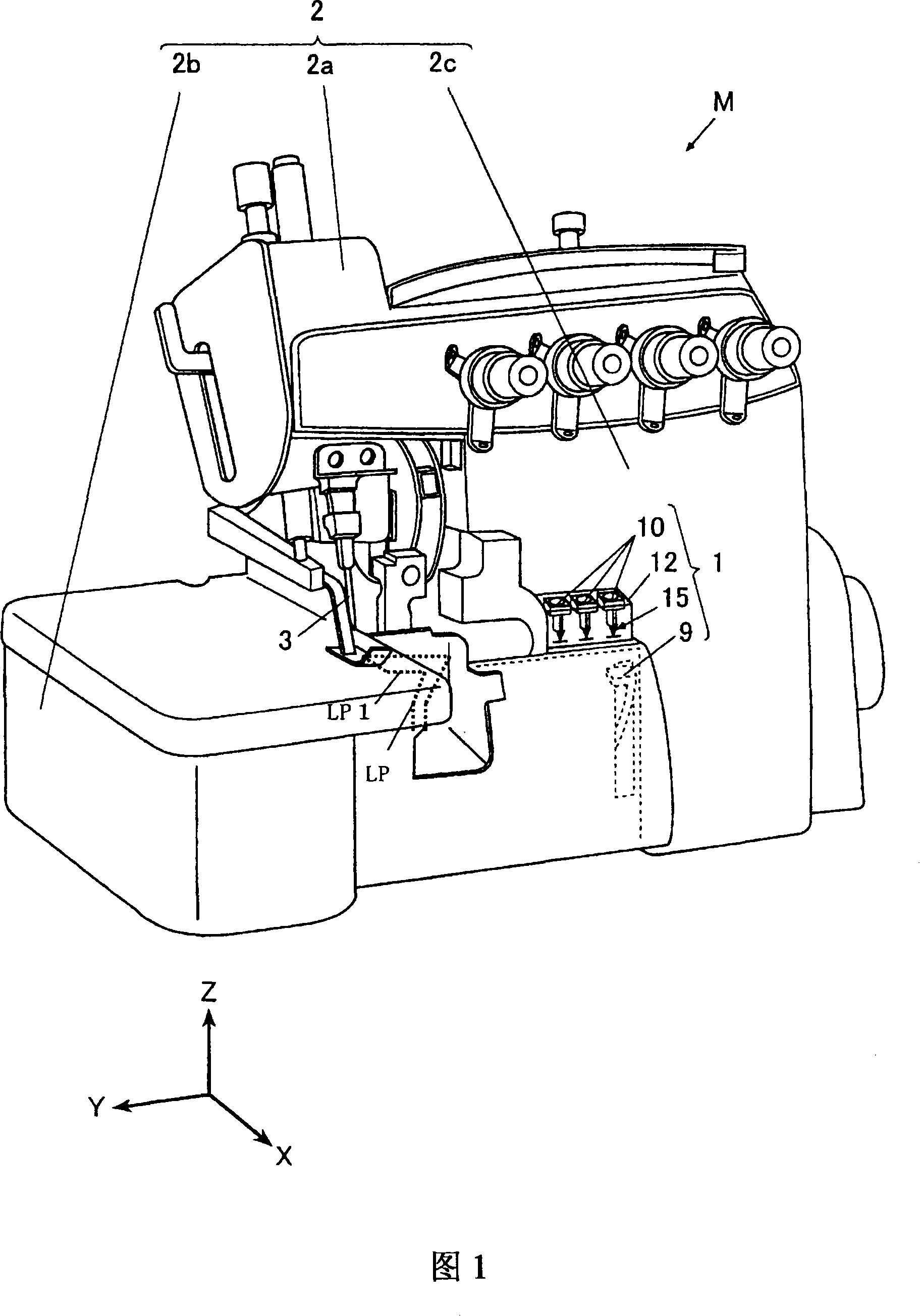
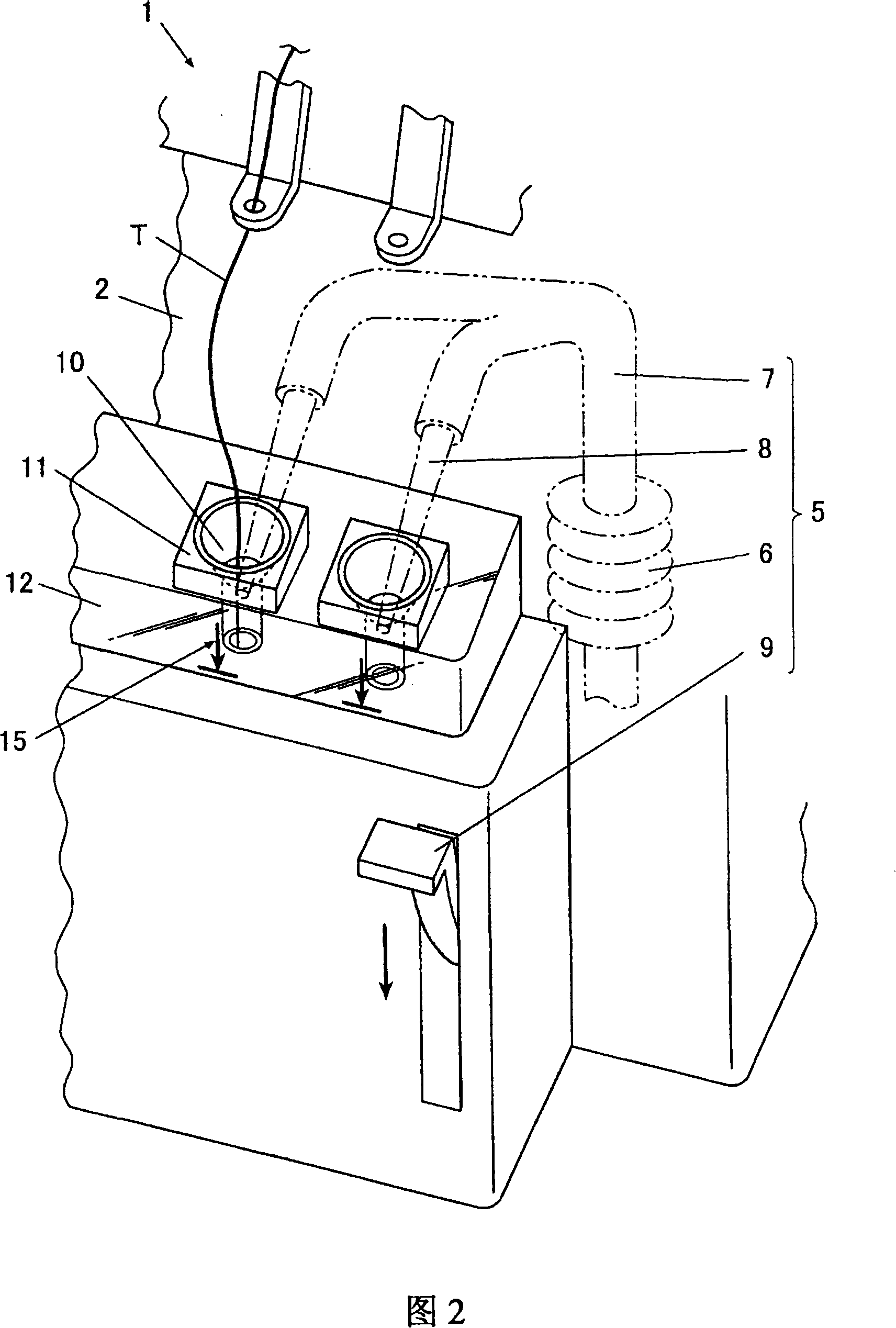
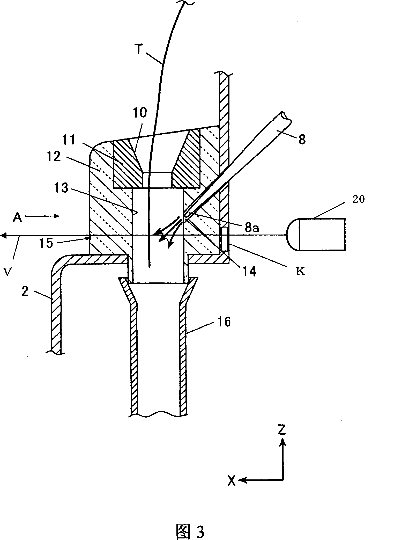
[0028] Hereinafter, the best mode for carrying out the present invention will be described in detail with reference to FIGS. 1 to 4 . However, in the embodiments described below, various technically preferable limitations are added in order to implement the present invention, but the scope of the invention is not limited to the following embodiments and illustrated examples. In addition, in this embodiment, the direction of each part of the sewing machine M is defined based on the XYZ axes shown in each drawing. In the state where the sewing machine M is installed on a horizontal surface, the Z-axis direction represents the vertical direction as the vertical direction, the Y-axis direction represents the left-right direction that coincides with the longitudinal direction of the sewing machine arm portion 2a, and the X-axis direction represents the horizontal direction and is aligned with the Y-axis direction. The direction is orthogonal to the front-back direction.

[0029] (...


PUM


Abstract

The tread is threaded through the curved needle easily. The threading device (1) comprises: a thread inserting base (12) with a thread way hole (13) having a thread inserting hole, namely aN opening part (10) outside the sewing machine frame (2) and an air way hole (14) converges with the thread way hole (13) near the opening part (10); and a air feed device (5), feeding compressed air to the air way hole (14). In the thread inserting base (12), at least the converging part of the thread way hole (13) and the air way hole (14) are formed by a transparent part, by which a thread (T) inserted from the opening (10) is recognized from the outside of the sewing machine frame (2), while the thread inserting part has a display portion (15) showing the inserting quantity mark of the thread (T) inserted from the opening (10).

Description

technical field [0001] The invention relates to a threading device for a sewing machine which uses air to convey thread for a looper to the vicinity of the looper. Background technique [0002] At present, as a sewing machine threading device for threading a sewing thread into a thread hole of a looper that cooperates with the sewing needle to form a stitch, there is known a technique that has an opening on the outside of the sewing machine frame, and at the same time leads to the sewing machine. Compressed air is blown into the suture channel inside the frame, that is, the inside of the thread pipe, and the suture is fed to the looper side (for example, refer to Patent Document 1). [0003] In the above-mentioned existing threading device, the air compressed by the air pump is ejected from the front end of the nozzle installed obliquely on the side of the aforementioned thread pipe through linkage with the control lever (refer to FIG. 5 ) manually operated by the operator, ...

Claims


Application Information

Patent Timeline
Patent Type & Authority Applications(China)
IPC IPC(8): D05B61/00D05B63/00D05B79/00
CPCD05B81/00D05B87/02
Inventor 贞末数也
Owner JUKI CORP
Why Eureka
Try Eureka