Projection device and its inner full-reflection prism

A technology of total reflection prisms and projection devices, applied in prisms, projection devices, optics, etc., can solve the problems of reducing image brightness, total reflection of illumination beam 102, and inability to be effectively used

Inactive Publication Date: 2008-04-30
CORETRONIC
View PDF0 Cites 6 Cited by
  • Summary
  • Abstract
  • Description
  • Claims
  • Application Information

AI Technical Summary

Problems solved by technology

However, since the refractive index of the second prism 120 is about 1.8, which is much larger than that of air, when the illuminating beam 102 is delivered to the light-emitting surface 124, part of the illuminating beam 102 is likely to be totally reflected due to an excessively large incident angle (such as the light beam 103 shown), so cannot be effectively utilized
Doing so will reduce the brightness of the image on the screen

Method used


Image

  • Projection device and its inner full-reflection prism
  • Projection device and its inner full-reflection prism
  • Projection device and its inner full-reflection prism

Examples


Embodiment Construction

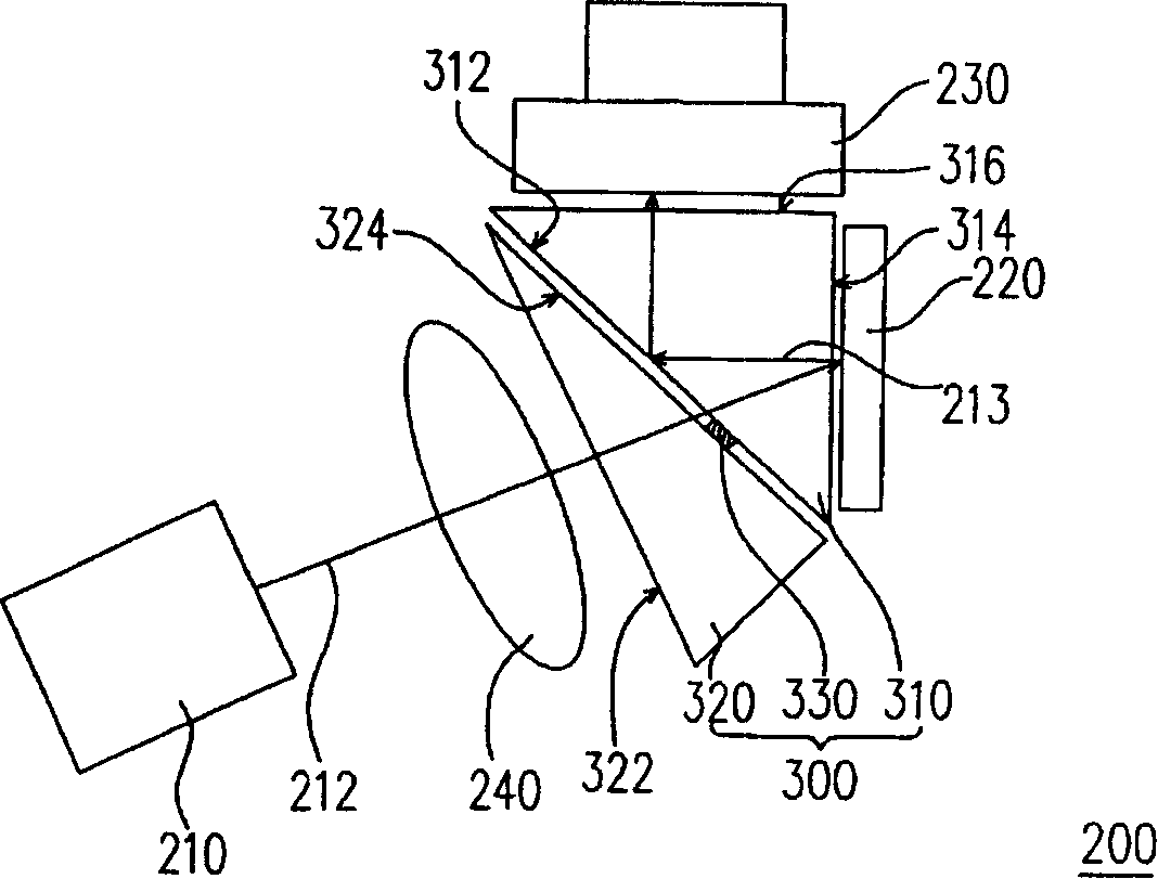
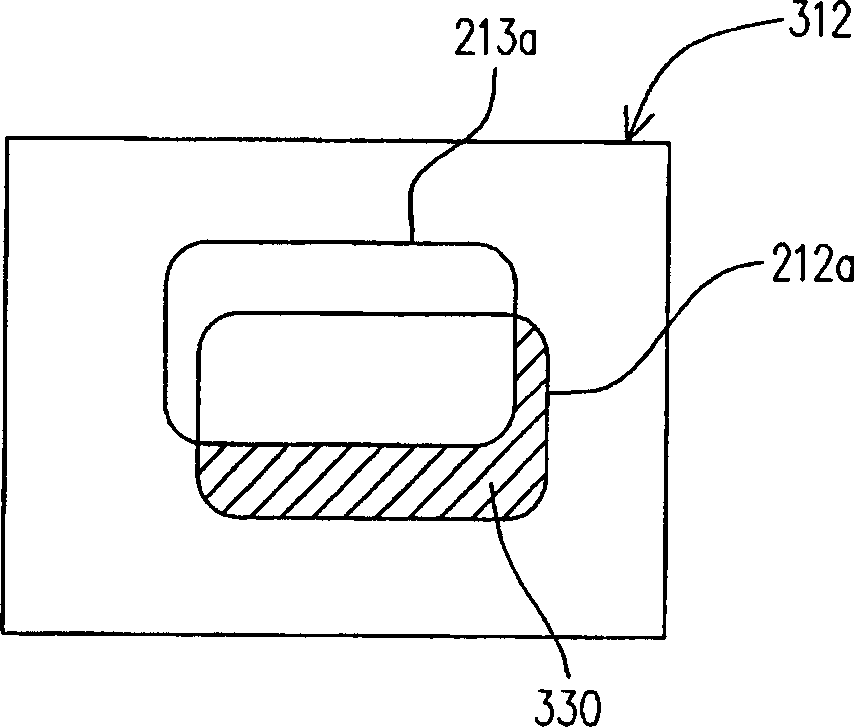
[0040] refer to Figure 2A , the projection device 200 of this embodiment includes an internal total reflection prism 300 , an illumination system 210 , a reflective light valve 220 and a projection lens 230 . The internal total reflection prism 300 includes a first prism 310 , a second prism 320 and an anti-total reflection layer 330 . The first prism 310 is, for example, a triangular prism, which has a first surface 312 , a second surface 314 , and a third surface 316 connected to form a triangle, wherein the first surface 312 , the second surface 314 , and the third surface 316 are, for example, flat. The second prism 320 is an optical path compensation prism, which is used to compensate the optical path difference of the light beam inside the first prism 310 . The second prism 320 has a light incident surface 322 and a light exit surface 324 , wherein the light exit surface 324 is opposite to the first surface 312 , and there is a gap between the light exit surface 324 an...


PUM


Abstract

The invention relates to the inner total-reflection prism of a projecting device, and consists of a first prism, a second prism and a total-reflection resistant layer. The first prism is provided with a first surface, a second surface and a third surface, while the second prism is provided with a light-in surface and a light-out surface. The light-out surface is opposite to the first surface, anda clearance is formed between the light-out surface and the first surface. The total-reflection resistant layer is connected between the part of the light-out surface and the part of the first surface. With the total-reflection resistant layer arranged, the probability of occurrences of total reflections in the inner total-reflection prism for illuminating rays is lowered, thereby, the utilization efficiency of the illuminating rays can be improved, and then the brightness of images are enhanced.

Description

technical field [0001] The present invention relates to a display device, and in particular to a projection device and a total internal reflection prism (total internal reflection prism, TIR prism) thereof. Background technique [0002] refer to figure 1 , the existing projection device 50 has an illumination system (illumination system) 52 , an internal total reflection prism 100 , a digital micro-mirror device (digital micro-mirror device, DMD) 54 and a projection lens 56 . The internal total reflection prism 100 is composed of a first prism 110 and a second prism 120 , wherein the first prism 110 is a triangular prism having a first surface 112 , a second surface 114 and a third surface 116 connected to form a triangle. The second prism 120 is an optical path compensation prism, which has a light incident surface 122 and a light exit surface 124, wherein the light exit surface 124 is opposite to the first surface 112, and there is an air gap (air gap) between the light e...

Claims


Application Information

Patent Timeline
Patent Type & Authority Applications(China)
IPC IPC(8): G03B21/00G02B5/04
Inventor 刘劲谷王思克
Owner CORETRONIC
Why Eureka
Try Eureka