Check patentability & draft patents in minutes with Patsnap Eureka AI!

Plasma display panel

A wrench and input shaft technology, applied in the field of wrenches, can solve the problems of being close to the outside of the rod, making it difficult for the staff to confirm the operation, and difficult to tighten the target screw, etc., to achieve the effect of great convenience and easy installation/separation operation

Inactive Publication Date: 2008-05-07
金南锡
View PDF1 Cites 3 Cited by
  • Summary
  • Abstract
  • Description
  • Claims
  • Application Information

AI Technical Summary

Problems solved by technology

In addition, the torque spring (torque spring) elastically supported between the inner wall surface of the gripping tube and the rod (rod) of the prior art can remain stable until the target nut is fully tightened, but compression occurs
On the contrary, after the target screw is fully tightened, the moving shaft can no longer rotate, so in this state, the torsion spring will rotate the handle with a greater counter force, so that the torsion spring can be compressed to the maximum, resulting in the phenomenon that the inner wall of the tube is too close to the outside of the rod
[0005] As a result, when the worker tightened the target screw, he had to check the compression degree of the torque spring (torque spring) one by one from the open part at the end of the clamp tube while rotating the handle, so it was difficult to perform the task of tightening the target screw.
Fully tighten the moving shaft and it can no longer rotate, so in this state, the torque spring will rotate the handle with a greater reaction force, so that the torque spring can be compressed to the maximum, so the direction of the end of the clamping tube cannot be kept consistent, and it often happens downwards , making it difficult for the staff to confirm the job

Method used


Image

  • Plasma display panel
  • Plasma display panel
  • Plasma display panel

Examples


no. 1 example

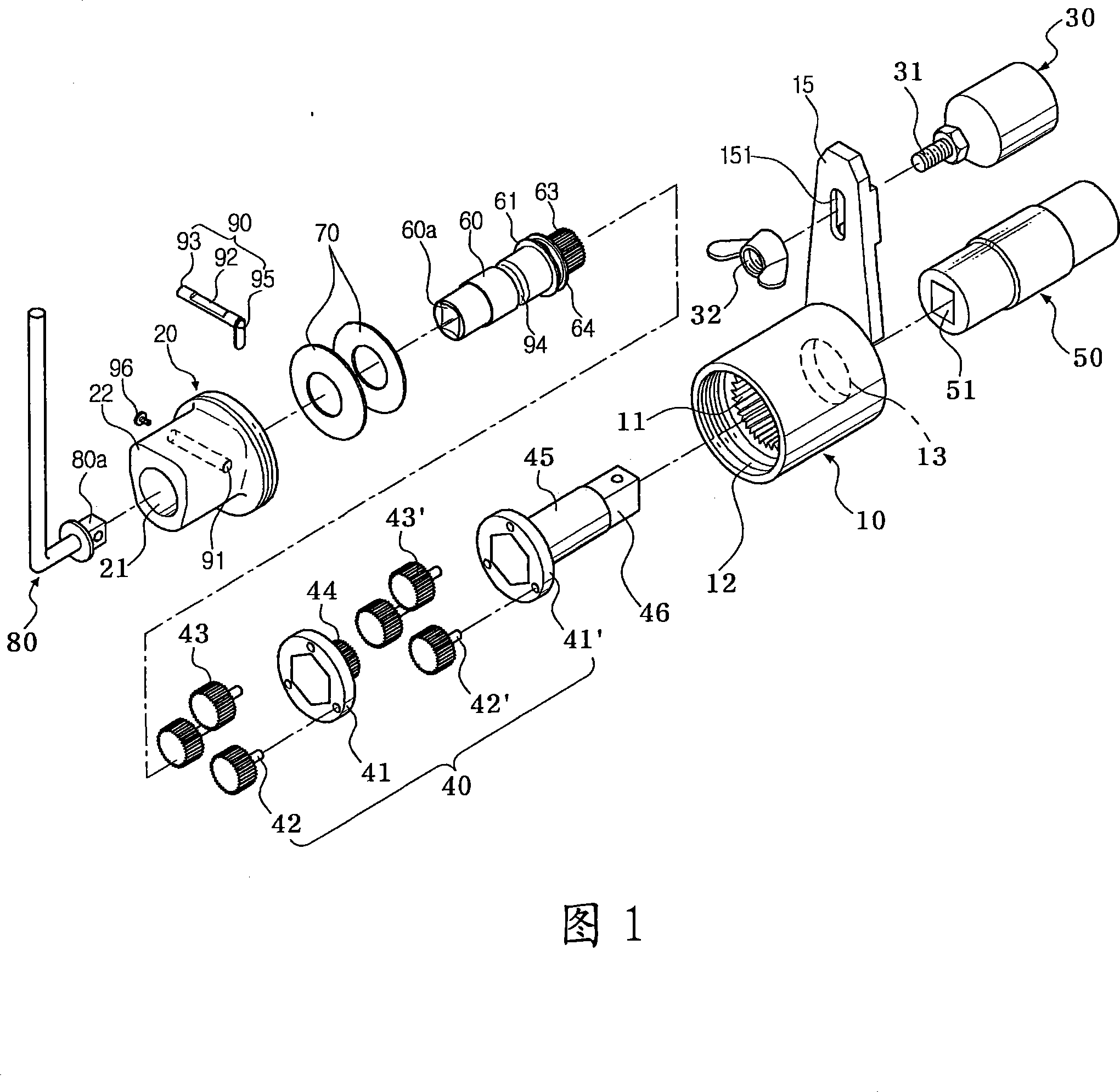
[0051]The tire wheels of a row of vehicles are fixed to the hub, and the product of the present invention is used when installing or removing fixing nuts on various fixing screw shafts protruding from the hub. When installing the set screw, it is not based on vision, but the idling state of the transmission gear, and immediately senses whether the set screw shaft is fully tightened, greatly improving convenience. In addition, clockwise or counterclockwise rotation can be used, making it easy to install or separate the fixing nut.

[0052] The wrench in the first practical operation example of the present invention is as Fig. 1 or Fig. 10, comprises cylindrical cover 10 and cap 20, the earliest input shaft 60, transmission gear 63, the earliest output shaft 45, elastic means 70, the first input shaft Stop / solve tool.

[0053] One side of the cover 10 is formed with an opening 12, and the other side has a support wall 14 having a diameter smaller than that of the opening of one...


PUM


Abstract

A wrench is provided to allow a user to recognize a completely fitted state of a fixing bolt by compressing ring plate springs through a flange of a driving shaft part and moving the flange to a rear side. A handle is mounted at rear ends of a driving shaft(60) by mounting a transmission(40) shaft-combined with a plurality of planetary gears(43) engaged with sun gears(11) to transfer the rotary force to a transmission, to transfer the rotary force to a socket(50) combined with a shear part of a transmission part(45), and to screw / release a fixing bolt. The driving shaft has a driving shaft part(61) formed with a plurality of clutches and a driving gear part(61') engaged with inner parts of the planetary gears. A plurality of ring plate springs(70) are placed between a rear surface of a flange(62) and an inner surface of a cap(20) to move the driving shaft through elastic rebound force. Further, the plurality of clutches contain a plurality of projections, a plurality of flat surfaces, a plurality of inclined planes.

Description

technical field [0001] The present invention relates to wrench. A device for attaching or removing a fixing nut to an object, for example, in order to fix a tire wheel of a vehicle on a wheel hub, the fixing nut is installed on or separated from a variety of fixing screw shafts protruding from the hub. It is a wrench that provides the best convenience by quickly sensing the fully tightened state of the set nut by moving the idling state of the gear instead of visually when installing the set nut. Background technique [0002] Tighten or loosen the setscrew. The device for tightening or loosening the fixing screw when the tire wheel of the vehicle is fixed to the wheel hub generally uses a wrench, which can quickly tighten or loosen the fixing nut even with the smallest force, and it may be convenient for women or the elderly to use. This product has been patented in the United States (License Notice: No. 6,742,417, hereinafter referred to as "Online Licensed Technology"). ...

Claims


Application Information

Patent Timeline
IPC IPC(8): B25B17/02B25B23/142B25B23/00
CPCB25B13/00B25B23/1422B25G1/00
Inventor 河龙秀
Owner 金南锡
Features
  • R&D
  • Intellectual Property
  • Life Sciences
  • Materials
  • Tech Scout
  • Unparalleled Data Quality
  • Higher Quality Content
  • 60% Fewer Hallucinations
Learn More