Image driving method and its system and LCD using the same

A driving method and image technology, applied to static indicators, cathode ray tube indicators, instruments, etc., can solve the problem of lowering display quality and achieve the effect of eliminating residual image color difference

Active Publication Date: 2008-05-07
INNOLUX CORP
View PDF1 Cites 2 Cited by
  • Summary
  • Abstract
  • Description
  • Claims
  • Application Information

AI Technical Summary

Problems solved by technology

Whether it is figure 2 or Figure 4 , the discolored afterimage will mak...

Method used


Image

  • Image driving method and its system and LCD using the same
  • Image driving method and its system and LCD using the same
  • Image driving method and its system and LCD using the same

Examples


Embodiment Construction

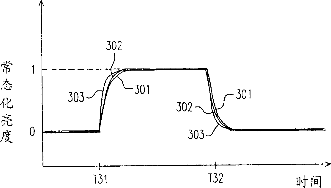
[0062] Fig. 5A, Fig. 5B, and Fig. 5C are the clock diagrams of the video signal and the pixel driving of each primary color light according to the embodiment of the present invention. The clock diagram shows that when the video signal changes from a luminance value of 96 to a luminance value of 192, the pixel performs overdrive The point in time of the applied voltage. FIG. 5A is a clock diagram of an image signal after frequency multiplication processing, FIG. 5B is a clock diagram of an overdrive by red and green pixels, and FIG. 5C is a clock diagram of an overdrive by blue pixels. This embodiment is a pixel driving method of a flat panel display of a scanning backlight module. The flat panel display is a liquid crystal flat panel display, so the light transmission medium is liquid crystal. The pixel driving method adopted in this embodiment provides multiple different overdrive corresponding tables for a certain primary color, so there are different multiple overdrive corr...


PUM


Abstract

The invention discloses an image drive method and a system as well as a liquid crystal display (LCD); wherein, the image drive method comprises the following steps: an overdrive operation for a pixel of a piece of primary color on a flat-panel display is implemented, a plurality of overdrive corresponding tables are provided to different primary colors, and the periods of the response time of the light-transmitting media for transmitting the primary color lights are differentiated to eliminate the aberration due to image persistence. Furthermore, the overdrive operation can be segmented into a plurality of overdriven operations to enhance the operating effects. The method has advantage of eliminating the image persistence aberration, which is caused by the different generating periods of the primary color lights of a scanning backlight unit on the flat-panel display. The image drive system comprises an overdrive circuit module and a display unit; the LCD comprises another overdrive circuit module, a source electrode drive circuit, a grid electrode drive circuit and a thin-film transistor liquid crystal panel.

Description

technical field [0001] The invention relates to a driving method and its system and a liquid crystal display using the same, in particular to an image driving method and its system and a liquid crystal display using the same. Background technique [0002] The backlight modules of the existing liquid crystal flat panel display are divided into two types: hold type and scan type. The hold-on backlight module is continuously on to supply the light source for the liquid crystal display panel. This hold-on backlight module has proved to have a major disadvantage, that is, insufficient response to moving images. When a fast moving image is displayed on the screen, because the switching response time of the liquid crystal pixel unit is too slow, the image will not be converted in time, and a shadow with a lighter grayscale will appear behind the moving object, which is the so-called afterimage phenomenon. [0003] figure 1 It is to illustrate the dynamic image response curve (MPR...

Claims


Application Information

Patent Timeline
IPC IPC(8): G09G3/34G09G3/36G09G3/20G09G5/02G02F1/133
Inventor 林弘裕石清文陈宥烨
Owner INNOLUX CORP
Why Eureka
Try Eureka