Parallel flow type heat converter
A heat exchanger, parallel flow technology, applied in the direction of fluid circulation arrangement, evaporator/condenser, lighting and heating equipment, etc., can solve the problem that the heat exchange efficiency cannot be fully exerted at the same time, so as to improve the heat exchange efficiency and overcome the junction. Cream, the effect of the best combination
- Summary
- Abstract
- Description
- Claims
- Application Information
AI Technical Summary
Problems solved by technology
Method used
Image
Examples
Embodiment 1
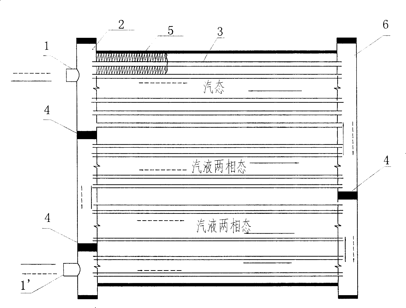
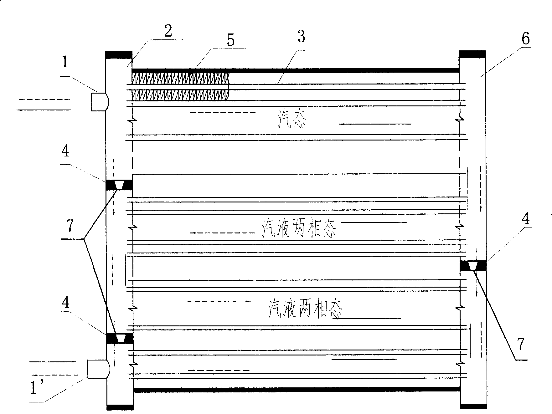
[0030] Such as figure 2 As shown, it shows a specific embodiment of the parallel flow heat exchanger of the present invention, the heat exchanger has a liquid collector 2, 6 on the left and right, and flat holes are punched out on the liquid collector 2, 6, After the flat tube 3 is inserted into the flat hole, it is fixed between the two liquid collecting pipes 2 and 6, and the fins 5 are placed between the liquid collecting pipes 2 and 6, and are formed by one-time welding in a furnace. Grooves are formed on the outside of the liquid collecting pipes 2 and 6 .
[0031] The dividing plate 4 is placed in the groove opened by the liquid collecting pipes 2 and 6 and is welded and sealed, and the dividing plate 4 divides the liquid collecting pipes 2 and 6 into a plurality of cavities.
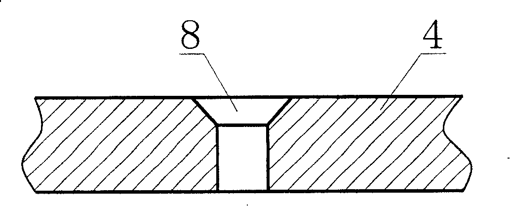
[0032] At least one partition 4 is provided with a one-way valve that can change the number of processes and the number of flat tubes in each process, or an orifice 8 that forms different flow c...
Embodiment 2
[0037] The throttling device of the present invention can have various forms. In the second embodiment of the present invention, a check valve 10 is used to replace the orifice 8 in the first embodiment, and other features are the same as those in the first embodiment.
[0038] This one-way valve 10 can be the common form in the prior art, as Figure 5-7 As shown, a spring is housed in the one-way valve 10, which can be opened one-way only under a certain pressure difference. One-way valve 10 can be installed on one or more or all partitions 4 . The one-way sealing function can also be realized without spring in the one-way valve, relying on gravity or pressure difference.
[0039] When applied in a heat pump system, the heat exchanger can realize different flow characteristics under cooling and heating conditions. That is to say, the same heat exchanger can have different passages in cooling and heating cycles. Figure 8A and Figure 8B What is shown is the state of the s...
Embodiment 3
[0046] In order to install a one-way valve or a throttle valve more conveniently, in the third embodiment of the present invention, the first and second embodiments are further improved, as Figure 11 As shown, the liquid collecting pipes 2 and 6 are divided into several sections, and a connecting pipe is used to communicate between the two cavities of the liquid collecting pipes 2 and 6, and a throttling device is installed in the middle of the connecting pipe, and other parts are the same as those in the embodiment One and two are the same. The throttling device in this embodiment may be the above-mentioned throttling hole or a one-way valve, so as to achieve different circulation paths of the refrigerant and achieve the best cooperation between the condenser and the evaporator under the heat pump working condition.
PUM
 Abstract
Description
Claims
Application Information
 - R&D
- Intellectual Property
- Life Sciences
- Materials
- Tech Scout
- Unparalleled Data Quality
- Higher Quality Content
- 60% Fewer Hallucinations
Browse by: Latest US Patents, China's latest patents, Technical Efficacy Thesaurus, Application Domain, Technology Topic, Popular Technical Reports.
© 2025 PatSnap. All rights reserved.Legal|Privacy policy|Modern Slavery Act Transparency Statement|Sitemap|About US| Contact US: help@patsnap.com


