
Packing type dust remover

A technology of dust collector and packing type, which is applied in chemical instruments and methods, separation of dispersed particles, filtration of dispersed particles, etc. It can solve the problems of difficult to achieve dust removal effect, damage to desulfurization and denitrification equipment, poor treatment effect, etc., and achieve novel structure , long service life, temperature balance effect

Active Publication Date: 2012-11-07
安徽和京能源科技有限公司
View PDF6 Cites 0 Cited by
  • Summary
  • Abstract
  • Description
  • Claims
  • Application Information

AI Technical Summary

Problems solved by technology

However, the treatment effect of some industrial flue gas with large temperature range and complex composition is poor. For example, the tail gas of heavy oil catalytic cracking unit (RFCC unit) has a temperature range of 170~400°C and a humidity of 10~12%. , the dust content is 300~500mg / Nm 3 , also contains SO 2 , NO x and other harmful substances
For the exhaust gas working conditions of the above-mentioned RFCC devices, if electrostatic precipitators and bag filter are used to remove dust, it is not only difficult to achieve the dust removal effect, but also easy to cause damage to the dust collectors; at the same time, such tail gas must be desulfurized and denitrified before being discharged. The dust removal stage with the dust collector is not adjusted for high temperature and huge temperature fluctuations, so it is very easy to cause damage to the desulfurization and denitrification equipment

Method used


Image

  • Packing type dust remover
  • Packing type dust remover
  • Packing type dust remover

Examples


Embodiment 1

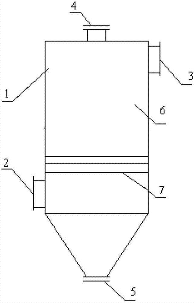
[0028] Such as figure 1 As shown, a packing type dust collector includes a housing 1 with a flue gas inlet 2 and a flue gas outlet 3, a packing inlet 4 is provided on the top of the housing 1, and a packing outlet 5 is provided at the bottom of the housing 1 , a packing area 6 is provided in the housing 1, and an isolation and air-permeable layer 7 is provided below the packing area 6, wherein the smoke inlet 2 and the smoke outlet 3 are arranged on the side wall of the housing 1, and the smoke outlet 3 It is arranged on the upper part of the side wall of the casing 1 , and the smoke inlet 2 is arranged on the lower part of the side wall of the casing 1 and is located below the insulating air-permeable layer 7 .

[0029] In the above embodiment, the isolation air-permeable layer 7 can block the filler so that the filler does not leave the filler area 6. At the same time, it can also make the flue gas pass smoothly into the filler area and contact the filler; Ceramic balls, th...

Embodiment 2

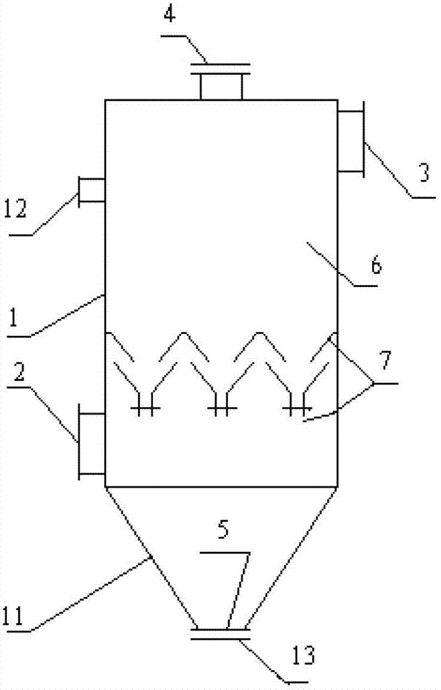
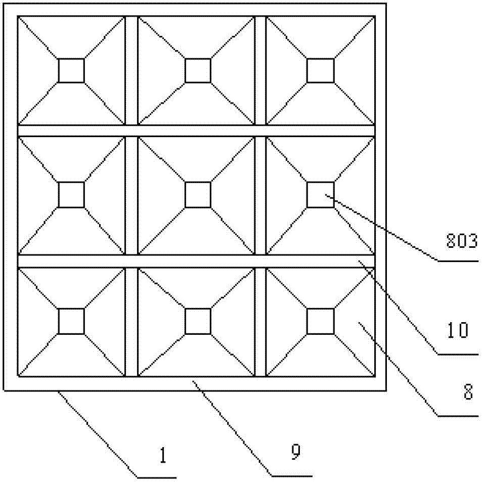
[0032] Such as figure 2 and image 3 Shown, a kind of packed dust collector, its structure and setting are the same as embodiment 1, and difference is:

[0033] The isolation air-permeable layer 6 is a double-set bucket layer, and nine double-set buckets 8 are arranged on the double-set bucket layer, and each double-set bucket 8 is connected to each other through a support device; the support device includes an external support frame connected to each other 9 and the inner support beam 10; wherein, the number of double-set buckets 8 vertically arranged on the double-set bucket layer is the same as the number of double-set buckets arranged horizontally, three rows are arranged vertically, three rows are arranged horizontally, and each row There are three, a total of nine;

[0034] Below the isolation air-permeable layer 6 is a discharge hopper 11 connected to the filler outlet 5;

[0035] An observation port 12 is also provided on the side wall of the housing 1;

[0036] A...

Embodiment 3

[0047] Such as figure 2 , image 3 and Figure 4 Shown, a kind of packing dust collector, its structure and setting are the same as embodiment 2, and difference is:

[0048] The diameter of the ceramic balls 14 is 3 mm to 10 mm. After the ceramic balls of this specification are piled up, the smoke and dust can be attached and the gaseous matter can be separated and discharged. At the same time, it is easy to maintain good mechanical properties, which is beneficial to reuse and avoids waste;

[0049] The flue gas inlet 2 and the flue gas outlet 3 are provided with pressure gauges (not shown in the figure), so as to know the pressure difference in the shell in time, and then understand the degree of saturation of the filler in the shell to absorb dust, so that according to the bearing capacity of the shell Depending on the pressure, switch the dust collector or replace the packing in time, so that the dust removal effect can be fully guaranteed.

[0050] The process and prin...


PUM

PropertyMeasurementUnit
diameteraaaaaaaaaa
diameteraaaaaaaaaa
diameteraaaaaaaaaa

Abstract

The invention relates to a packing type dust remover comprising a shell provided with an exhaust gas inlet and an exhaust gas outlet, wherein the top of the shell is provided with a packing inlet, the bottom of the shell is provided with a packing outlet, the shell is internally provided with a packing area; an isolation ventilation layer is arranged below the packing area; the exhaust gas inlet and the exhaust gas outlet are arranged on the side wall of the shell, wherein the exhaust gas outlet is arranged on the upper part of the side wall of the shell while the exhaust gas inlet is arranged on the lower part of the side wall of the shell and arranged below the isolation ventilation layer. The packing type dust remover is suitable for each working condition, particularly the complex working condition for exhaust gas dust removing treatment, and meanwhile, the exhaust gas temperature is greatly decreased and the exhaust gas distribution is adjusted in order to ensure the subsequent treatment; besides, the dust remover has advantages of stable structure and flexible packing treatment so as to be suitable for being popularized and applied to an exhaust gas dust removing treatment technology in the fields of power generation, petrochemical industry and the like.

Description

technical field [0001] The invention relates to a flue gas dedusting mechanical device, in particular to a packing type deduster. Background technique [0002] At present, dust collectors are widely used in mining, building materials, food, pharmaceutical, metallurgy, chemical and other industries to deal with smoke and dust exhaust gas. The dust collectors used mainly include electrostatic precipitators and bag dust collectors. The dust removal technology is relatively mature and the dust removal effect is relatively good. . However, the treatment effect of some industrial flue gas with large temperature range and complex composition is poor. For example, the tail gas of heavy oil catalytic cracking unit (RFCC unit) has a temperature range of 170~400°C and a humidity of 10~12%. , the dust content is 300~500mg / Nm 3 , also contains SO 2 , NO x and other harmful substances. For the exhaust gas working conditions of the above-mentioned RFCC devices, if electrostatic precip...

Claims


Application Information

Patent Timeline
Patent Type & Authority Applications(China)
IPC IPC(8): B01D46/30
Inventor 艾淑艳
Owner 安徽和京能源科技有限公司
Learn More