Intelligent dust-removal and ventilating system

A ventilation system, intelligent technology, applied in ventilation system, space heating and ventilation, space heating and ventilation details, etc., can solve the problem of poor exhaust effect of ventilation devices, inability to effectively adjust ventilation volume, and large demand for ventilation volume and other problems, to achieve the effect of improving dust removal efficiency, reducing labor costs, and increasing ventilation volume

Inactive Publication Date: 2018-10-23
INST OF LASER & OPTOELECTRONICS INTELLIGENT MFG WENZHOU UNIV
View PDF9 Cites 8 Cited by
  • Summary
  • Abstract
  • Description
  • Claims
  • Application Information

AI Technical Summary

Problems solved by technology

[0003] Existing ventilation devices are generally provided with a negative pressure fan in the air duct for strong ventilation, and filter the sundries and dust in the air through the filter screen installed in the air duct. The dust and dust gradually accumulate on the filter screen, blocking the filter holes of the filter screen, resulting in poor exhaust effect of the ventilation device, requiring frequent replacement of the filter screen, and high cost of use; and according to different seasons, factories have different requirements for ventilation volume , during summer production, the temperature inside the factory is higher than the outside world, and people have a greater demand for ventilation; during winter production, the temperature inside the factory is lower than the outside world. The device cannot effectively adjust the ventilation volume according to seasonal changes

Method used


Image

  • Intelligent dust-removal and ventilating system

Examples


Embodiment Construction

[0028] The following is further described in detail through specific implementation methods:

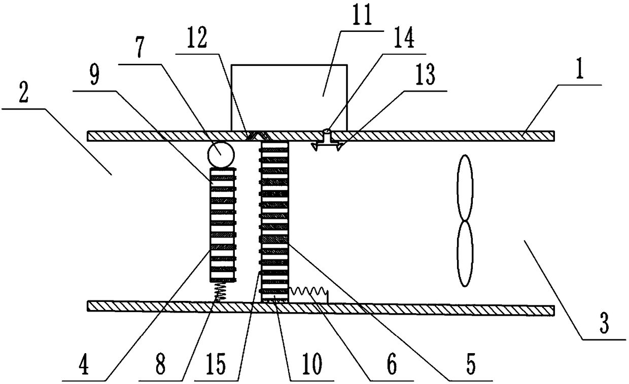
[0029] The reference signs in the drawings of the description include: channel 1, air inlet 2, air outlet 3, first filter plate 4, second filter plate 5, reset member 6, air bag 7, elastic member 8, through hole 9, fine hole 10. Water tank 11, nozzle hole 12, nozzle 13, solenoid valve 14, soft brush 15.

[0030] like figure 1 As shown, the intelligent dust removal and ventilation system of the present invention includes a channel 1 with an air inlet 2 and an air outlet 3, the channel 1 is arranged along the horizontal direction, and a negative pressure fan located at the air outlet 3 in the channel 1, the channel in this embodiment The shape can be a hollow cuboid, and the bottom wall of the channel 1 is slightly inclined downward along the direction of the air outlet 3;

[0031] A first filter plate 4 and a second filter plate 5 that can be attached are arranged in parallel in the...


PUM


Abstract

The invention discloses an intelligent dust-removal and ventilating system and relates to the field of air purification devices. The intelligent dust-removal and ventilating system comprises a channel. A first filtering plate and a second filtering plate which can be attached are arranged in the channel, and the first filtering plate is slidably connected with the inner wall of the channel in thevertical direction. The second filtering plate is slidably connected with the inner wall of the channel in the horizontal direction. An airbag is fixedly connected to the top of the first filtering plate, and the other side of the airbag is fixedly connected with the top wall of the channel. An elastic piece is arranged between the bottom of the first filtering plate and the bottom wall of the channel, and a through hole is formed in the first filtering plate. A slim hole is formed in the second filtering plate, and the communicating area of the through hole and the slim hole is increased gradually in the process of downward moving of the first filtering plate. A water tank is arranged on the upper portion of the channel, a plurality of spray holes communicating with the water tank are formed in the top wall of the channel, and when the second filtering plate and the first filtering plate are attached, the spray holes can be shielded. The problems that an existing ventilating device isprone to being blocked and cannot automatically adjust the ventilation quantity according to the environment temperature are solved, and the intelligent dust-removal and ventilating system is mainlyused for ventilating and dust removal of a factory.

Description

technical field [0001] The invention relates to the field of air purification devices, in particular to an intelligent dust removal ventilation system. Background technique [0002] In factories that process cement, flour, and grain, a large amount of dust will be generated. These dusts floating in the air of the processing plant will cause serious damage to the respiratory system of workers, and will cause people's vision to be blurred, which is prone to various operations. ACCIDENT. Moreover, the equipment, circuits, and instruments deposited by dust will accelerate the corrosion and aging of the equipment, affecting heat dissipation and equipment life. It will also affect the safety and clean production of enterprises. Therefore, it is necessary to use a ventilation device to extract these dusts outside the factory. [0003] Existing ventilation devices are generally provided with a negative pressure fan in the air duct for strong ventilation, and the sundries and dust...

Claims


Application Information

Patent Timeline
Patent Type & Authority Applications(China)
IPC IPC(8): F24F7/06F24F13/28
CPCF24F7/065F24F13/28
Inventor 林礼区
Owner INST OF LASER & OPTOELECTRONICS INTELLIGENT MFG WENZHOU UNIV
Why Eureka
Try Eureka