Control method of non-sensor permenant-magnetic synchronous motor
A synchronous motor and permanent magnet technology, applied in motor control, motor generator control, AC motor control, etc., can solve the problems of sensor failure and high total cost, and achieve vibration prevention, stable and quiet low-speed rotation, and cost reduction. Effect
- Summary
- Abstract
- Description
- Claims
- Application Information
AI Technical Summary
Problems solved by technology
Method used
Image
Examples
Embodiment 1
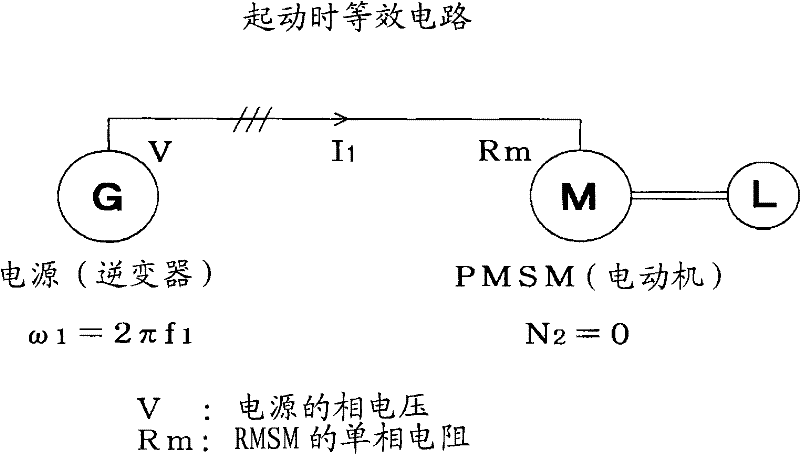
[0027] The so-called synchronous starting method is one of the ways to start the synchronous motor powered by three-phase AC power supply, such as Figure 6 As shown, both the synchronous generator G on the driving side and the synchronous motor M on the driven side are used as synchronous equipment. In the stopped state, the three-phase terminals of the two are connected to each other and the excitation current flows respectively. When starting, use The driving device D directly connected to the synchronous generator G rotates slowly, then the synchronous generator G rotates and supplies the ultra-low frequency current to the synchronous motor M, and the magnetic field generated by the rotating magnetic field and the excitation current generated on the side of the synchronous motor M It works to synchronize the synchronous motor M with the synchronous generator G, and then continue to increase the synchronous speed by increasing the speed of the synchronous generator G until i...
Embodiment 2
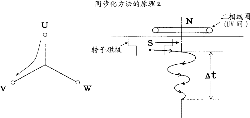
[0100] Next, a second embodiment of the synchronous activation method will be described. Such as image 3 As shown, in the three-phase coil, DC current flows into the two-phase coil first, and the rotor magnetic pole is attracted by the stator magnetic axis (non-rotating) generated thereby, and the magnetic axis is adjusted for synchronization, and then, like a common inverter device, Phase switching is performed between VW and WU to increase the frequency. Even in this case, a fixed time Δt of several seconds is required to align the initial magnetic poles with the magnetic axis (until the rotor is synchronized and stabilized while vibrating with natural vibration).
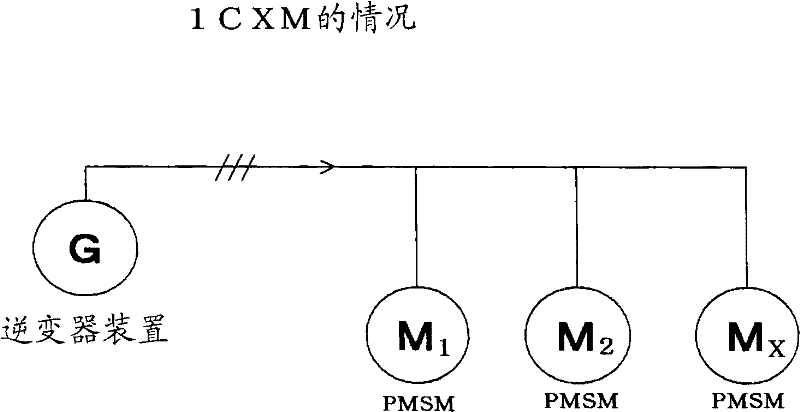
[0101] image 3 It is a diagram about one PMSM. When this method is applied to the start-up of two or more X PMSMs, although the synchronization conditions will be slightly stricter, it can be obtained by studying the resistance value of the PMSM, GD 2 , Applied voltage, etc. to achieve reliable synchronizati...
Embodiment 3
[0104] When sensorless PMSM is used such as a large air conditioner, the load directly connected to the PMSM is a blower, and the power supply is cut off to stop a certain PMSM group (two or more PMSMs operating with a single inverter device) At this time, the positive pressure environment caused by other running blowers exerts pressure on the stopped blower, which becomes the reverse rotation and rotates opposite to the normal state. Its speed can sometimes reach 40% of the rated speed.
[0105] The present invention proposes a method for reliably synchronizing with a single inverter power supply and stably starting even in the case of two or more sensorless PMSMs under such reverse rotation conditions.
[0106] If the two blowers have different power sources (inverter devices for each), at different speeds (for example, one is -N 3 min -1 , the other is -N 4 min -1 ) is rotating, in the case of 1C1M, connect the coils of each phase of the two PMSMs, and use the current f...
PUM
 Abstract
Description
Claims
Application Information
 - R&D
- Intellectual Property
- Life Sciences
- Materials
- Tech Scout
- Unparalleled Data Quality
- Higher Quality Content
- 60% Fewer Hallucinations
Browse by: Latest US Patents, China's latest patents, Technical Efficacy Thesaurus, Application Domain, Technology Topic, Popular Technical Reports.
© 2025 PatSnap. All rights reserved.Legal|Privacy policy|Modern Slavery Act Transparency Statement|Sitemap|About US| Contact US: help@patsnap.com


