
DC offset calibration method and apparatus

A technology of DC offset and calibration method, which is applied in the field of communication, can solve problems such as complex circuits and poor real-time performance, and achieve simple results

Inactive Publication Date: 2008-05-21
STATE GRID CORP OF CHINA +1
View PDF2 Cites 23 Cited by
  • Summary
  • Abstract
  • Description
  • Claims
  • Application Information

AI Technical Summary

Problems solved by technology

[0011] The present invention is made in consideration of the above problems. Therefore, the main purpose of the present invention is to provide a DC offset calibration solution to solve the problems of complex circuits and poor real-time performance in DC offset calibration in the related art.

Method used


Image

  • DC offset calibration method and apparatus
  • DC offset calibration method and apparatus

Examples


Embodiment Construction

[0030] method embodiment

[0031] In this embodiment, a DC offset calibration method is provided.

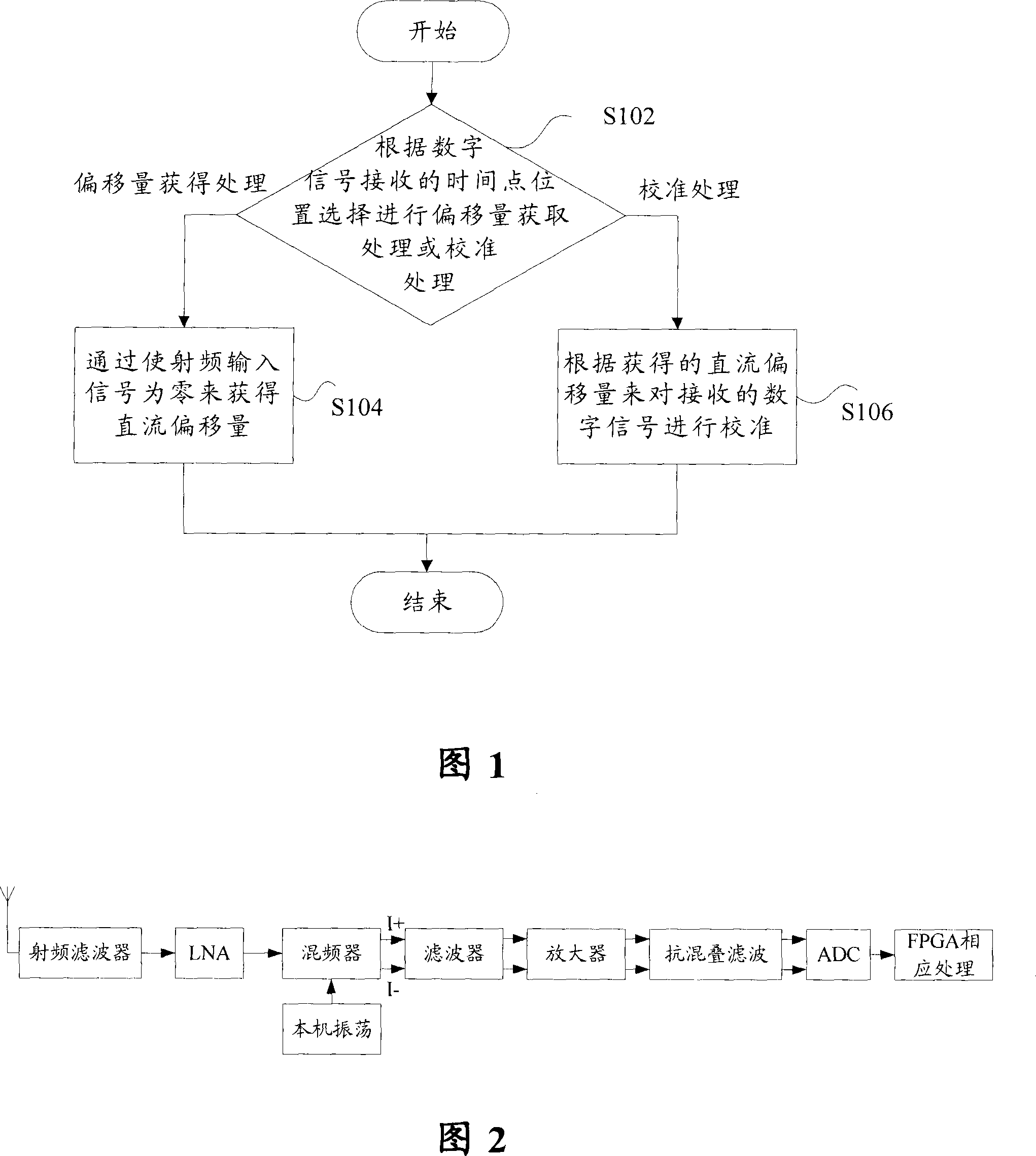
[0032] As shown in FIG. 1, the DC offset calibration method according to this embodiment includes: step S102, performing offset acquisition processing or calibration processing according to the time point position selection of digital signal (for example, IQ digital signal) reception; step S104, The offset obtaining process is to obtain the DC offset by making the radio frequency input signal zero; step S106 , the calibration process, to calibrate the received digital signal according to the obtained DC offset.

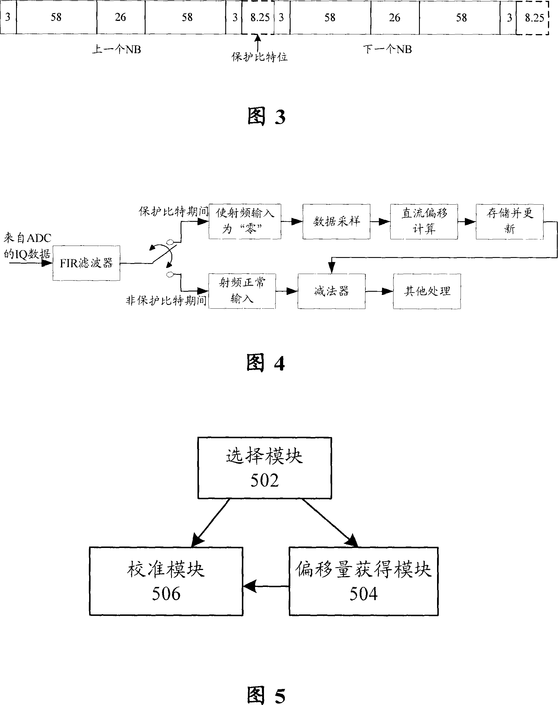
[0033] Wherein, when the position of the receiving time point of the digital signal is at the beginning moment of the time period when no valid data is received, the offset value acquisition process is started; the position of the receiving time point of the digital signal is at the time of receiving valid data In the case of a segment, calibration processing is perfor...


PUM


Abstract

The invention discloses a DC offset calibration method, comprising the following steps: selecting to acquire the offset value or take calibration according to the time point position of receiving the digital signal; the offset is processed - DC offset is obtained by returning the RF input signal to zero; calibration processing - calibrating the digital signal received according to the DC offset. Also, the invention discloses a DC offset calibration device. The invention has the advantages that with the method and the device, the DC offset variation caused by temperature variation, circuit parameter variation or other reasons can be traced and calibrated without adding any additional complicated analog circuit or affecting the normal operation of a base station, and also the invention is simple to be implemented.

Description

technical field [0001] The present invention relates to the field of communications, and in particular, to a method and device for calibrating a DC offset. Background technique [0002] Compared with the traditional double frequency conversion technology, the zero intermediate frequency technology uses only one frequency conversion. In the transmitting part, the mapped digital in-phase quadrature (IQ) signal passes through the DAC (Digital-to-Analog Converter, digital-to-analog converter) to become a quadrature analog IQ signal, and then directly modulates to the radio frequency without passing through the intermediate frequency filtering part ; In the receiving part, a mixer is used to directly change the in-band RF signal into an analog IQ signal, and then through an ADC (Analog-to-Digital Converter, analog-to-digital converter) into a digital IQ signal, and then decompose Digital baseband processing such as modulation and decoding. [0003] Compared with the traditional...

Claims


Application Information

Patent Timeline
Patent Type & Authority Applications(China)
IPC IPC(8): H04B1/10H04B1/30
Inventor 淦星星杭靠文崔亦军
Owner STATE GRID CORP OF CHINA
Learn More