Stent and method for manufacturing the same

A frame and component technology, applied in the field of stents and the manufacture of the stents, can solve problems such as reducing elastic force, product quality degradation, and damage to wire components, and achieve the effect of reducing pain

Active Publication Date: 2008-05-21
STANDARD SCI TECH
View PDF0 Cites 19 Cited by
  • Summary
  • Abstract
  • Description
  • Claims
  • Application Information

AI Technical Summary

Problems solved by technology

Therefore, in the above process, the wire member may be damaged, thereby reducing its elastic force and thus deteriorating the quality of the product.

Method used


Image

  • Stent and method for manufacturing the same
  • Stent and method for manufacturing the same
  • Stent and method for manufacturing the same

Examples


Embodiment Construction

[0024] The present invention will now be described more fully with reference to the accompanying drawings, in which exemplary embodiments of the invention are shown.

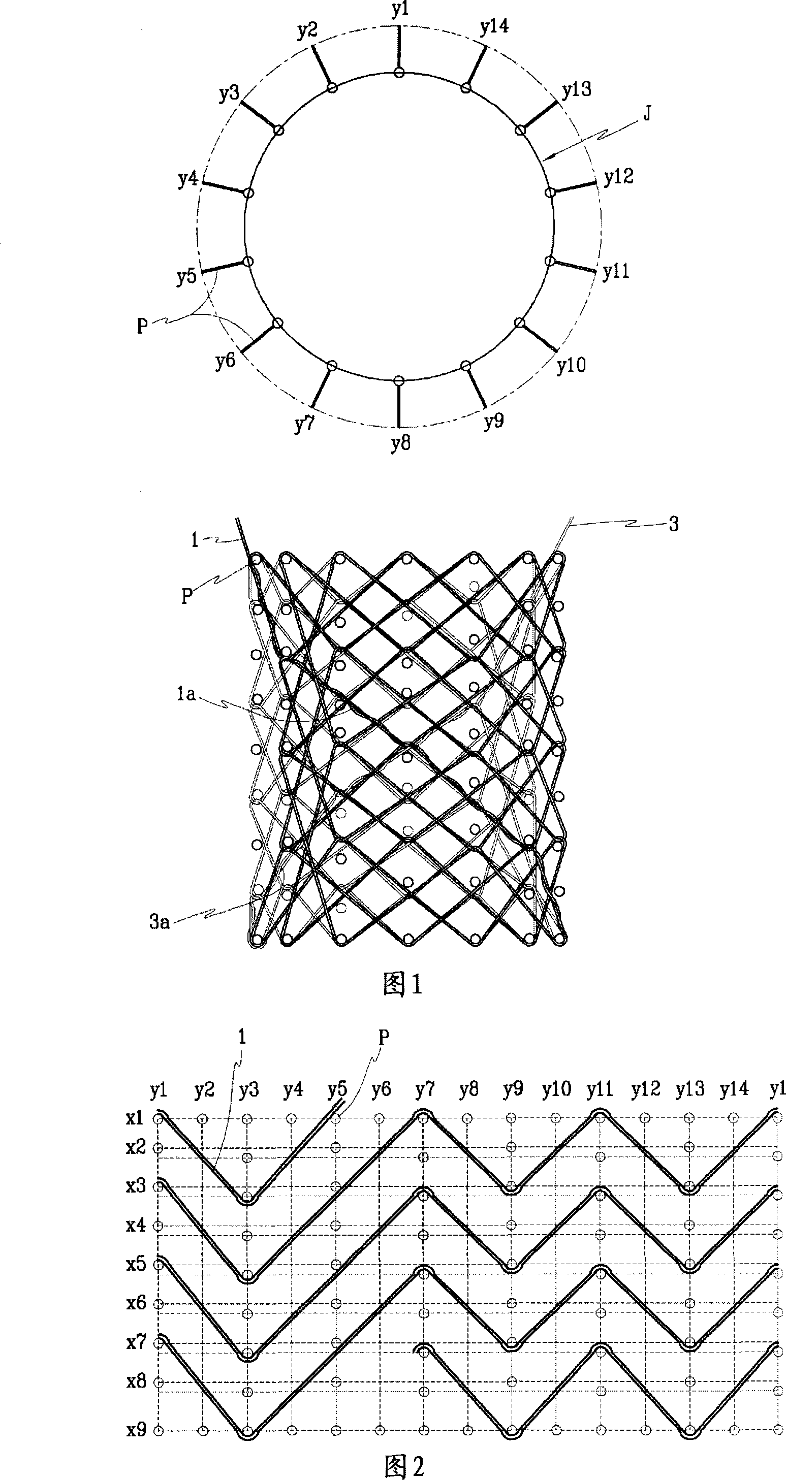
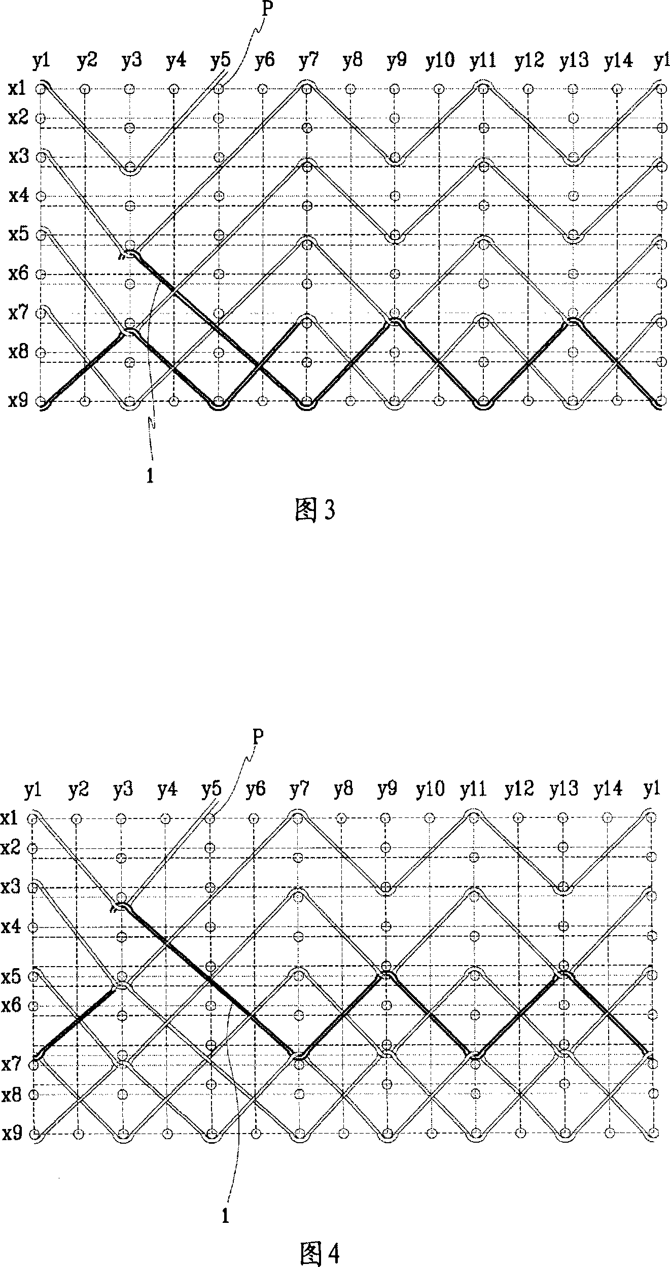
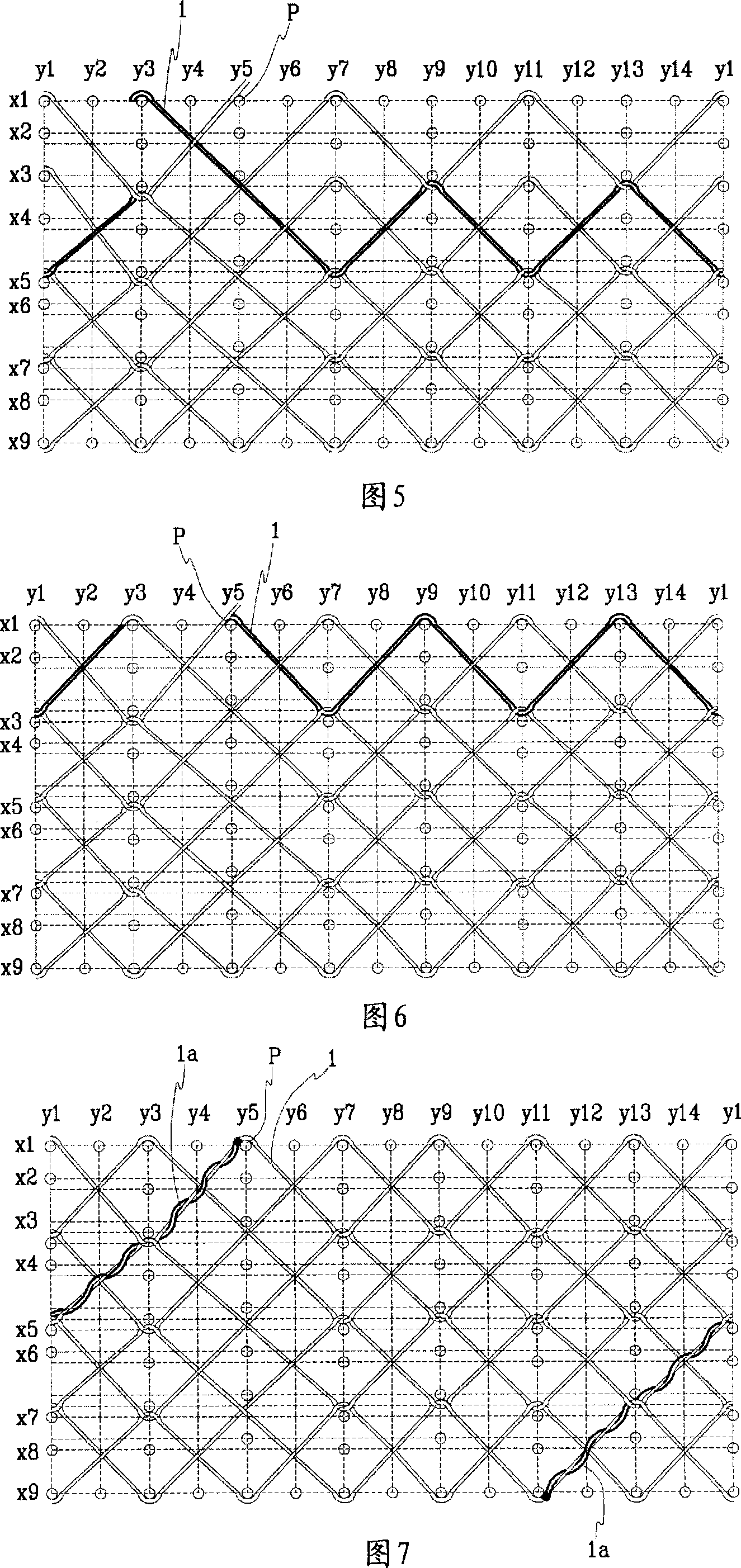
[0025] Figure 1 is a perspective view of a stent made by the method of the present invention. 2 to 14 are views showing a continuous process of manufacturing the stent.

[0026] According to an embodiment of the invention, the bracket is formed by a first member 1 and a second member 3 . 2 to 7 are views showing a process of forming a cylindrical bracket on a manufacturing frame from a first member. 8 to 14 are views illustrating a process of forming a fine mesh structure from the second member. A fine mesh structure is formed on the cylindrical support formed by the first member. The first member 1 and the second member 3 may be formed of wire members, which may be coated for medical use, to be inserted into cavities or lesions of the human body. A method of manufacturing a bracket using the manufacturing f...


PUM


Abstract

A method of manufacturing a stent includes forming a first cylindrical mesh structure by bending a first member in a zigzag-shape having peaks and valleys and a plurality of turns wound around an outer circumference of a manufacturing frame and forming a second cylindrical mesh structure by bending a second member in a zigzag-shape having peaks and valleys and a plurality of turns wound around an outer circumference of a manufacturing frame, wherein a bending track the second member crosses a bending track of the first member.

Description

technical field [0001] The present invention relates to a stent and a method for making the stent, and more particularly to a stent and a method for making the stent by preventing its material from being damaged during the manufacturing process. Improve the quality of brackets. Background technique [0002] Generally, a stent may be inserted into a lesion of a cavity or blood vessel of the body to maintain passage of the cavity or blood vessel. The stent may be formed from a shape memory alloy (eg, Nitinol) that maintains a uniform expansion force at the temperature of the lumen. The stent may be formed in a cylindrical shape braided with wires, and the cylindrical stent may be formed by sequentially and repeatedly braiding two thin and long members to have better expansion force (elasticity) in the radial direction. That is, a plurality of nails are arranged on a cylindrical manufacturing frame. The distance between the nails is the same as each other. Two thin and long...

Claims


Application Information

Patent Timeline
Patent Type & Authority Applications(China)
IPC IPC(8): A61F2/06
CPCD03D3/02D10B2509/06A61F2/90A61F2240/001A61F2/82A61F2/89A61F2/86
Inventor 安圣淳
Owner STANDARD SCI TECH
Why Eureka
Try Eureka