Chip cleaning device in nc processing machine

A technology of cleaning device and chip, applied in machine tool parts, metal processing machinery parts, maintenance and safety accessories, etc., to achieve the effect of improving chip removal ability, expanding cleaning range, and expanding reachable range

Inactive Publication Date: 2008-05-28
OKUMA CORP
View PDF2 Cites 9 Cited by
  • Summary
  • Abstract
  • Description
  • Claims
  • Application Information

AI Technical Summary

Problems solved by technology

Therefore, it is not possible to replace the tool with a chip cleaning unit in the tool box that is automatically kept on the spindle for cleaning

Method used


Image

  • Chip cleaning device in nc processing machine
  • Chip cleaning device in nc processing machine
  • Chip cleaning device in nc processing machine

Examples


Embodiment Construction

[0022] Embodiments of the present invention will be described below with reference to the drawings.

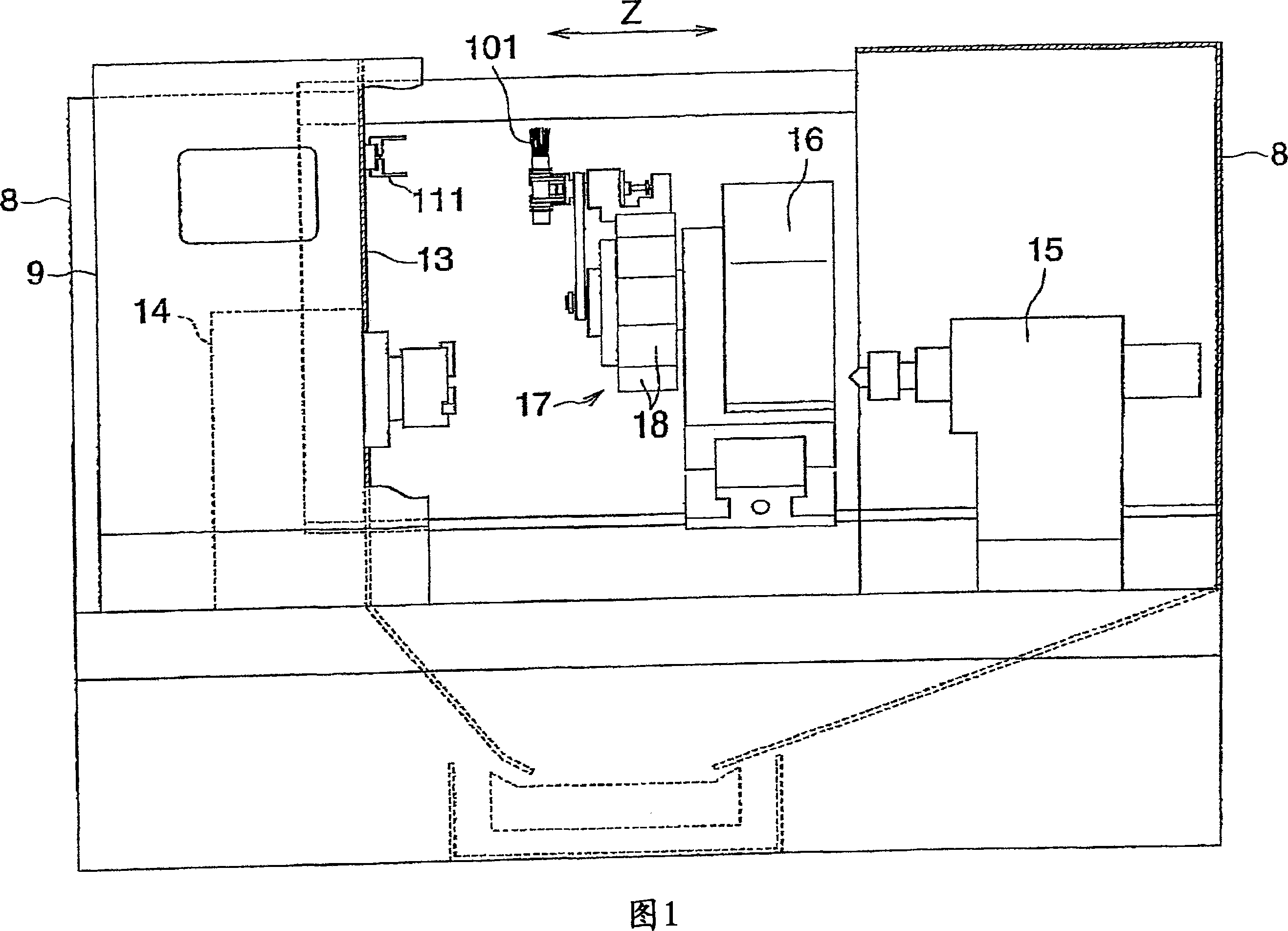
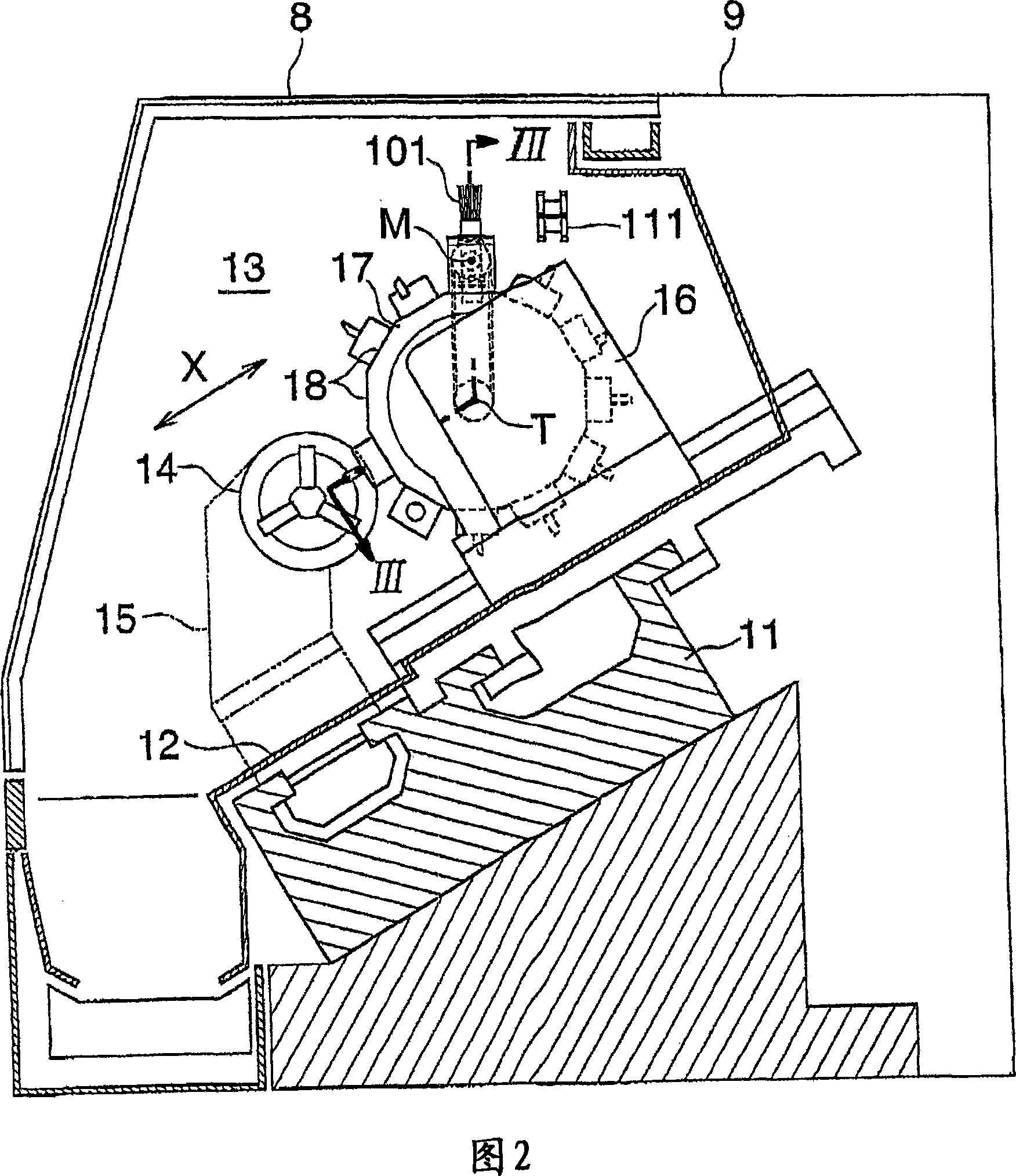
[0023] In Figure 1 and Figure 2, the overall structure of the CNC machine tool is shown. In the following description, the front-rear direction (Z-axis direction) means that the left side in FIG. left and right sides).

[0024] The bed 11 is provided with a right upper inclined top surface. The direction perpendicular to the Z direction and inclined along the top surface of the bed is the X direction. In the rear space of the partition cover 13, a processing chamber is formed by the outer cover 12 covering the right side from the top surface of the bed, the door 9 covering the integral cover 8 and a part of the notch of the integral cover, and the partition cover 13.

[0025] On the left side of the bed top surface, a headstock 14 and a tailstock 15 are mounted to face each other. The front end portion of the headstock 14 penetrates the partition cover 13 and enters the ma...


PUM


Abstract

There is provided an NC processing machine in which a cleaning operation is carried out automatically, instead of a processing operation. A turret having plural tool mounting surfaces at its outer peripheral surface is supported on a tool post which is movable in the directions of a Z axis and an X axis, such that the turret is rotatable about a T axis. A gripper shaft extending along an M axis parallel to the T axis and is spaced radially from the T axis is rotatably supported on one of the tool mounting surfaces of the turret. A movable gripper capable of detachably gripping a chip cleaning member is mounted to one end of the gripper shaft. A stationary gripper capable of detachably gripping the chip cleaning member is placed such that it can transfer and receive the chip cleaning member to and from the movable gripper within the range of movement caused by composite operations of the movement of the tool post in the directions of the Z axis and the X axis and the rotation of the turret about the T axis.

Description

technical field [0001] The invention relates to a chip cleaning device on a machine tool, in particular to a chip cleaning device on a CNC machine tool with a turning function such as a numerically controlled lathe, a numerically controlled compound lathe, and the like. Background technique [0002] Conventionally, it is well known that on a machine tool equipped with an automatic tool changer, when machining a workpiece, the tools necessary for machining are held on the main shaft, and the chip cleaning device is stored in the tool box to clean the parts scattered around the main shaft. In the case of chips, the tool is removed from the spindle and stored in the tool box, and instead of the tool, the chip cleaning member is held on the spindle, and the spindle is NC-operated to perform cleaning. (For example, refer to Patent Document 1 or Patent Document 2) [0003] In a numerically controlled machine tool having a turning function such as a numerically controlled lathe or...

Claims


Application Information

Patent Timeline
Patent Type & Authority Applications(China)
IPC IPC(8): B23Q11/00
CPCB23Q2230/002B23Q11/0042B23Q2220/002Y10T29/5154Y10T409/304088
Inventor 小豆泽隆彦栗山纯一
Owner OKUMA CORP
Why Eureka
Try Eureka