Distributor tube subassembly

Inactive Publication Date: 2009-07-09
DELPHI TECH INC
View PDF27 Cites 43 Cited by
  • Summary
  • Abstract
  • Description
  • Claims
  • Application Information

AI Technical Summary

Benefits of technology

[0011]Accordingly, the present invention provides efficient installation of a refrigerant conduit in a header and provides a heat exchanger which is also compatible with traditional heat exchanger components and systems. The conduit body portion of the refrigerant conduit is

Problems solved by technology

Inserting a refrigerant conduit into a header without damaging the refrigerant tubes or the refrigerant conduit is often difficult in a residential heat exchanger because of the increased length.
However, wh

Method used


Image

  • Distributor tube subassembly
  • Distributor tube subassembly
  • Distributor tube subassembly

Examples


Embodiment Construction

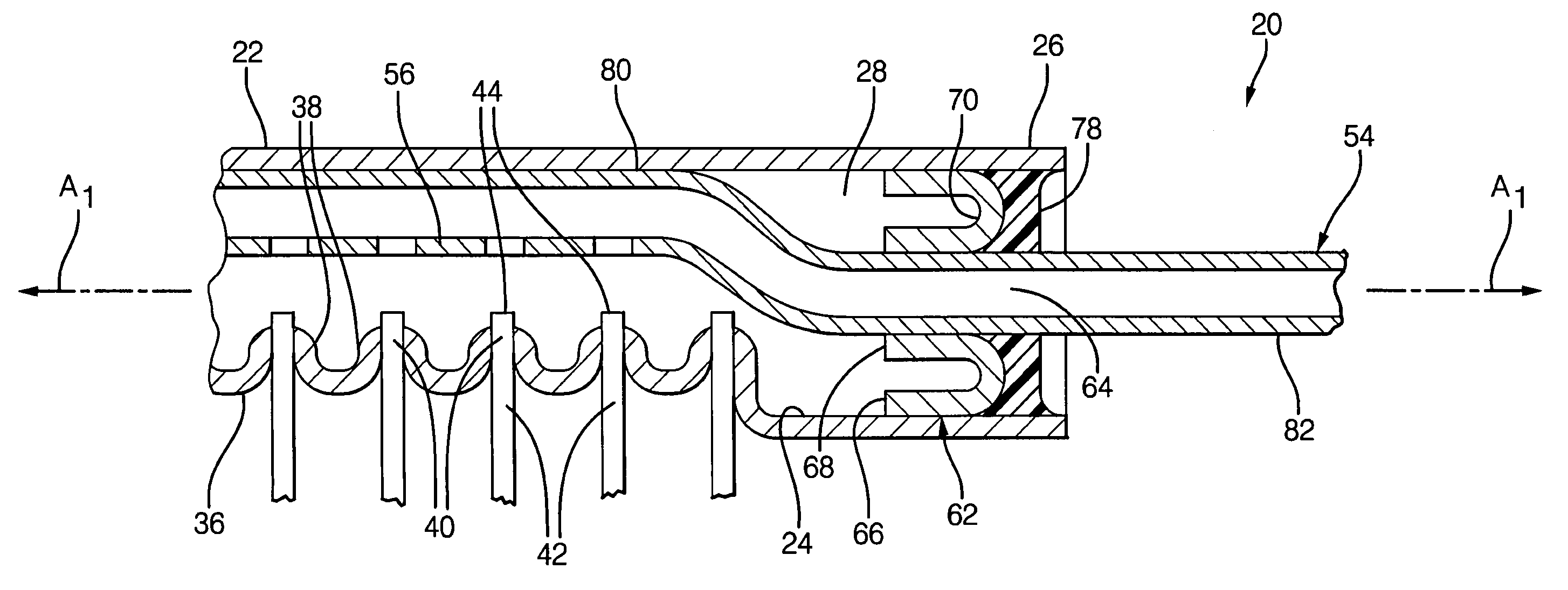
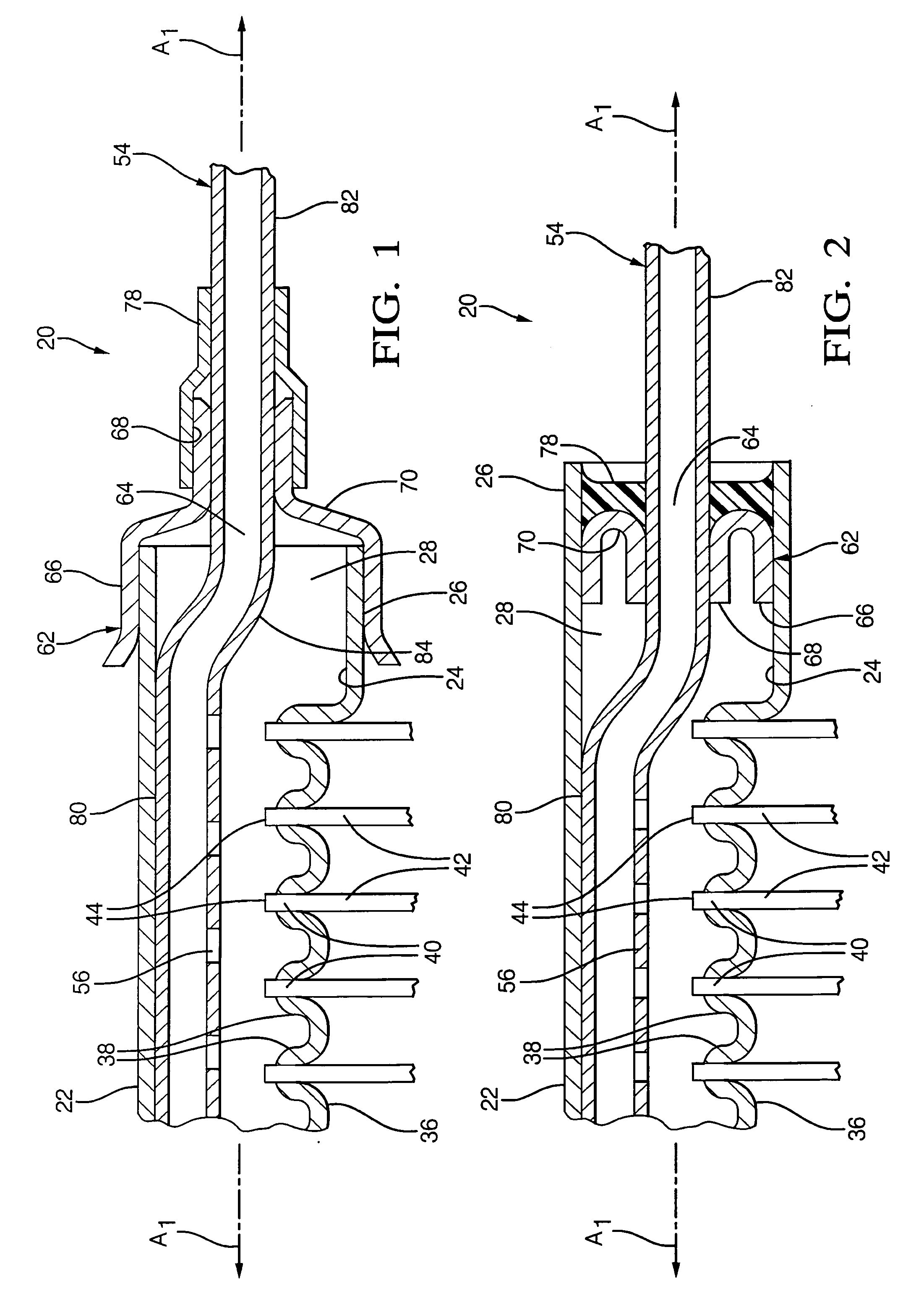
[0018]Referring to the Figures, wherein like numerals indicate corresponding parts throughout the several views, a heat exchanger assembly 20 for dissipating heat is shown generally.

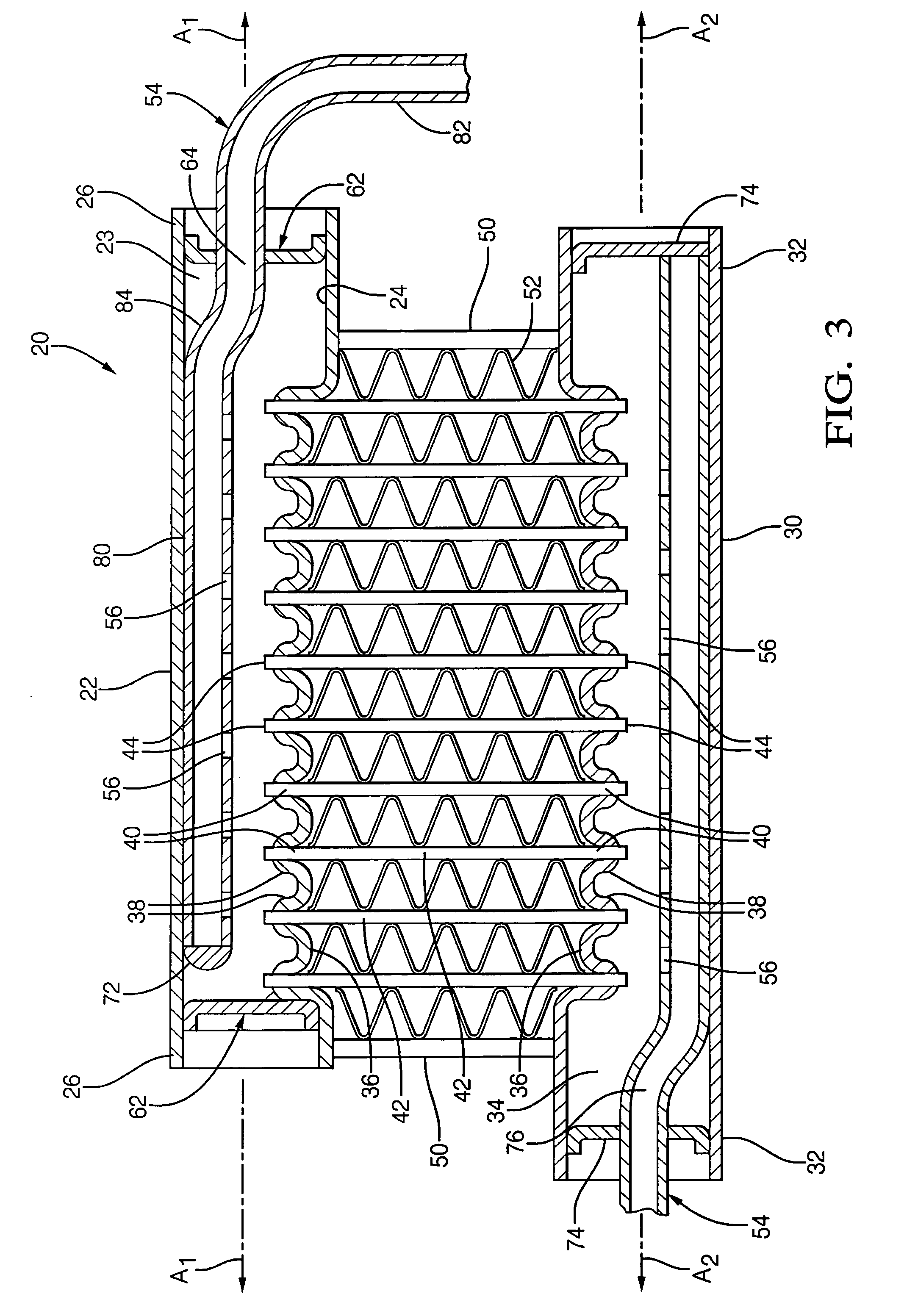
[0019]The heat exchanger assembly 20 comprises a first header 22, generally indicated, having an interior surface 24 and being generally circular in cross-section. The first header 22 extends along a first header axis A1 between a pair of first header end portions 26 to define a first cavity 28. A second header 30 is generally indicated and generally circular in cross-section. The second header 30 extends along a second header axis A2 between a pair of second header end portions 32 to define a second cavity 34. As shown in FIG. 3, the second header axis A2 is preferably parallel to the first header axis A1.

[0020]Hereinafter, an exemplary embodiment of the heat exchanger assembly 20 is described wherein the first header 22 is an outlet header 22 and the second header 30 is an inlet header 30. However, it ...


PUM


Abstract

A heat exchanger assembly includes an outlet header extending along an outlet axis to define an outlet cavity and an inlet header defining an inlet cavity. A plurality of refrigerant tubes extends from the inlet header through the outlet header and into the outlet cavity. A collector conduit is disposed in the outlet header and includes a conduit body portion and at least one conduit end portion interconnected by a conduit transition portion with the conduit body portion being offset from the conduit end portion. The conduit body portion is engaged to an interior surface of the outlet header to space the conduit body portion from the refrigerant tubes extending into the outlet header and the conduit end portion is coaxial with the outlet header axis to provide a central outlet for the refrigerant vapor.

Description

CROSS REFERENCE TO RELATED APPLICATION[0001]This application claims the benefit of application Ser. No. 61 / 020,040 filed on Jan. 9, 2008.BACKGROUND OF THE INVENTION[0002]1. Field of the Invention[0003]The subject invention relates generally to a heat exchanger and method of fabricating the same, and, more specifically to a heat exchanger of the type including a plurality of refrigerant tubes extending between an inlet header and an outlet for transferring refrigerant from the inlet header to the outlet header.[0004]2. Description of the Prior Art[0005]Due to their high performance, automotive style brazed heat exchangers are being developed for residential air conditioning and heat pump applications. Automotive heat exchangers typically utilize a pair of headers with refrigerant tubes defining fluid passages to interconnect the headers. Residential heat exchangers are typically larger than automotive heat exchangers and generally require headers that are two to five times longer tha...

Claims


Application Information

Patent Timeline
IPC IPC(8): F28F9/02B21D53/02
CPCF28D1/05383Y10T29/4935F28F9/0273F28F9/028
Inventor BEAMER, HENRY E.MCGREEVY, THOMASRUNK, ROBERT M.WINTERSTEEN, DOUGLAS C.SAMUELSON, DAVID E.
Owner DELPHI TECH INC
Why Eureka
Try Eureka