Inner rail gauge for scribing large diameter circular arc

A large-diameter, arc-shaped technology, applied in the field of scribing tools, can solve the problems of non-reusable, low scribing accuracy, and inconvenient operation, and achieves the effect of high arc scribing accuracy.

Inactive Publication Date: 2008-05-28
HUDONG ZHONGHUA SHIPBUILDINGGROUP
View PDF0 Cites 3 Cited by
  • Summary
  • Abstract
  • Description
  • Claims
  • Application Information

AI Technical Summary

Problems solved by technology

[0006] The purpose of the present invention is to overcome the shortcomings of the above-mentioned prior art and provide an inner rail gauge for drawing large-diameter arcs to solve the problems of low marking accuracy, inconvenient operation and non-reusable use in the prior art

Method used


Image

  • Inner rail gauge for scribing large diameter circular arc
  • Inner rail gauge for scribing large diameter circular arc
  • Inner rail gauge for scribing large diameter circular arc

Examples


Embodiment 1

[0033] The present invention will be described in detail below with a scribing and positioning tool with a large-diameter arc of a specific structure. Its structure is as follows:

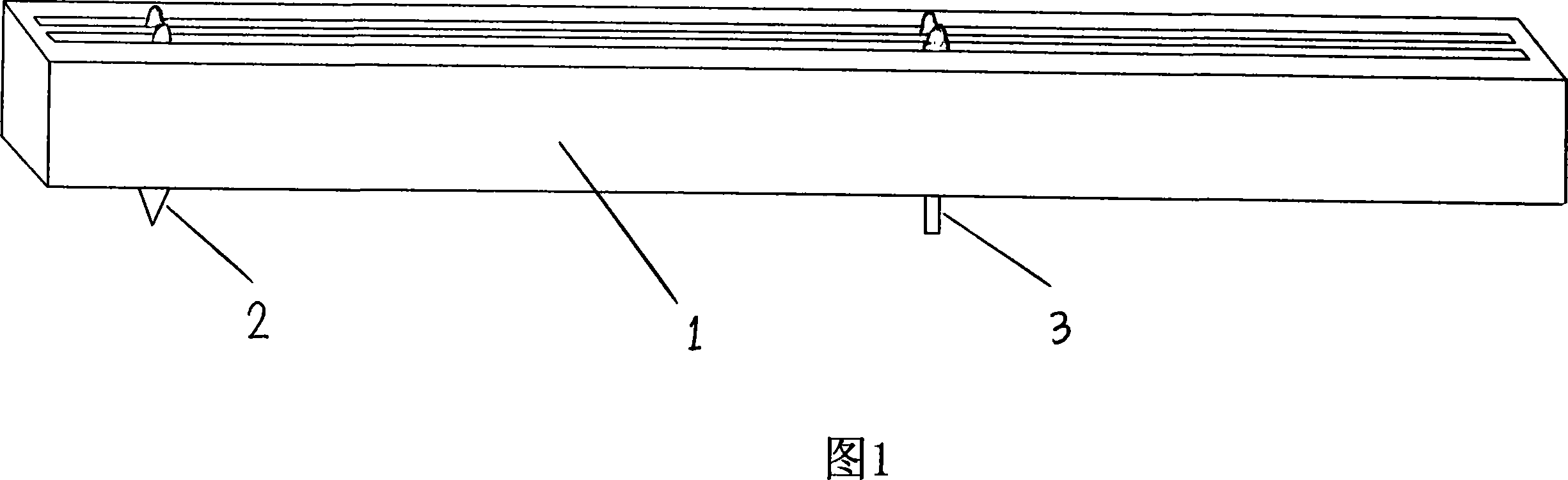
[0034] The inner rail gauge with a large diameter arc, its main structure mainly includes a linear gauge rod 1, a circle center slider 2 embedded in the inner groove of the gauge rod 1, and a center slider embedded in the inner groove of the gauge rod 1 The dash slider in 3. The profile of the center slider 2 and the marking slider 3 is similar to the profile of the inner groove of the gauge rod 1 and slightly smaller than the inner edge of the inner groove, so the two sliders can be embedded in the Slip back and forth in the longitudinal position in the inner groove of the gauge rod 1, but basically it will not affect its transverse position. The inner groove of the gauge rod 1 is larger than the outer contour of the two sliders, so that it can slide arbitrarily in the inner groove, that is, the...

Embodiment 2

[0040] The structure of embodiment 2 is basically the same as that of embodiment 1, the difference is:

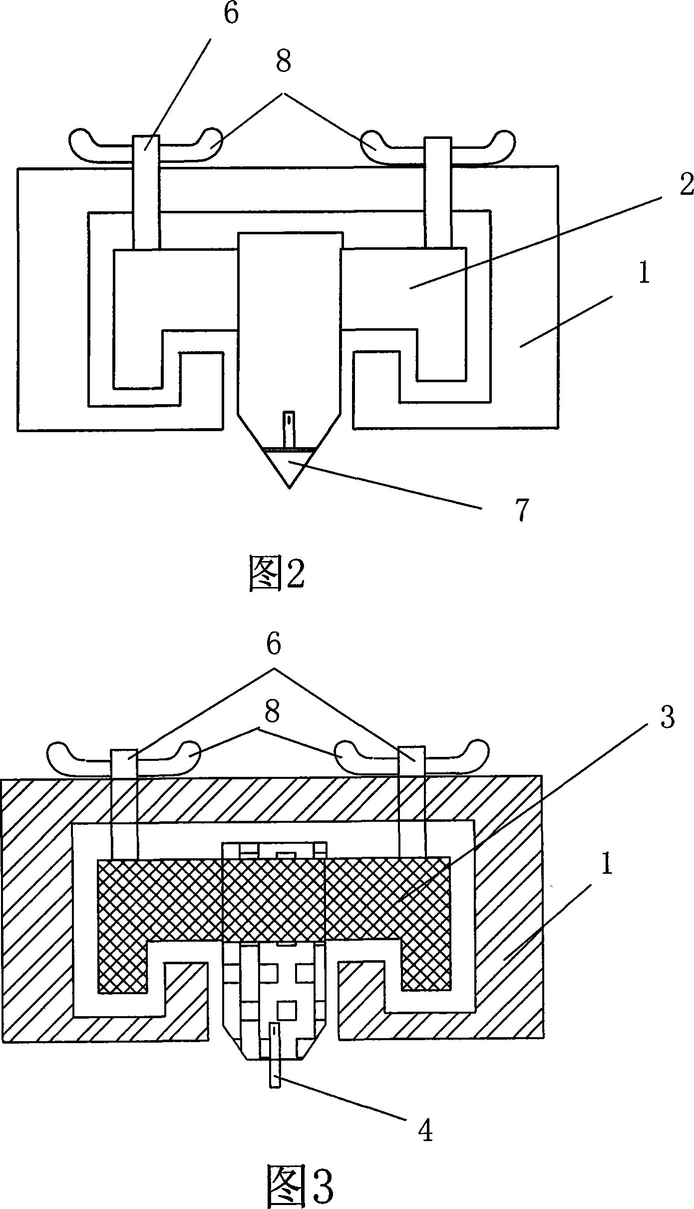
[0041] First, the scale is engraved on one side of the upper through groove of the gauge bar 1, and the centers of the wing nuts 8 of the circle center slider 2 and the marking slider 3 are respectively set to indicate their positions. Guided by the red line, the precise position of the circle center slider 2 or the marking slider 3 can be known, and then the distance between the two can be accurately determined to realize the precise setting of the radius of the drawn arc.

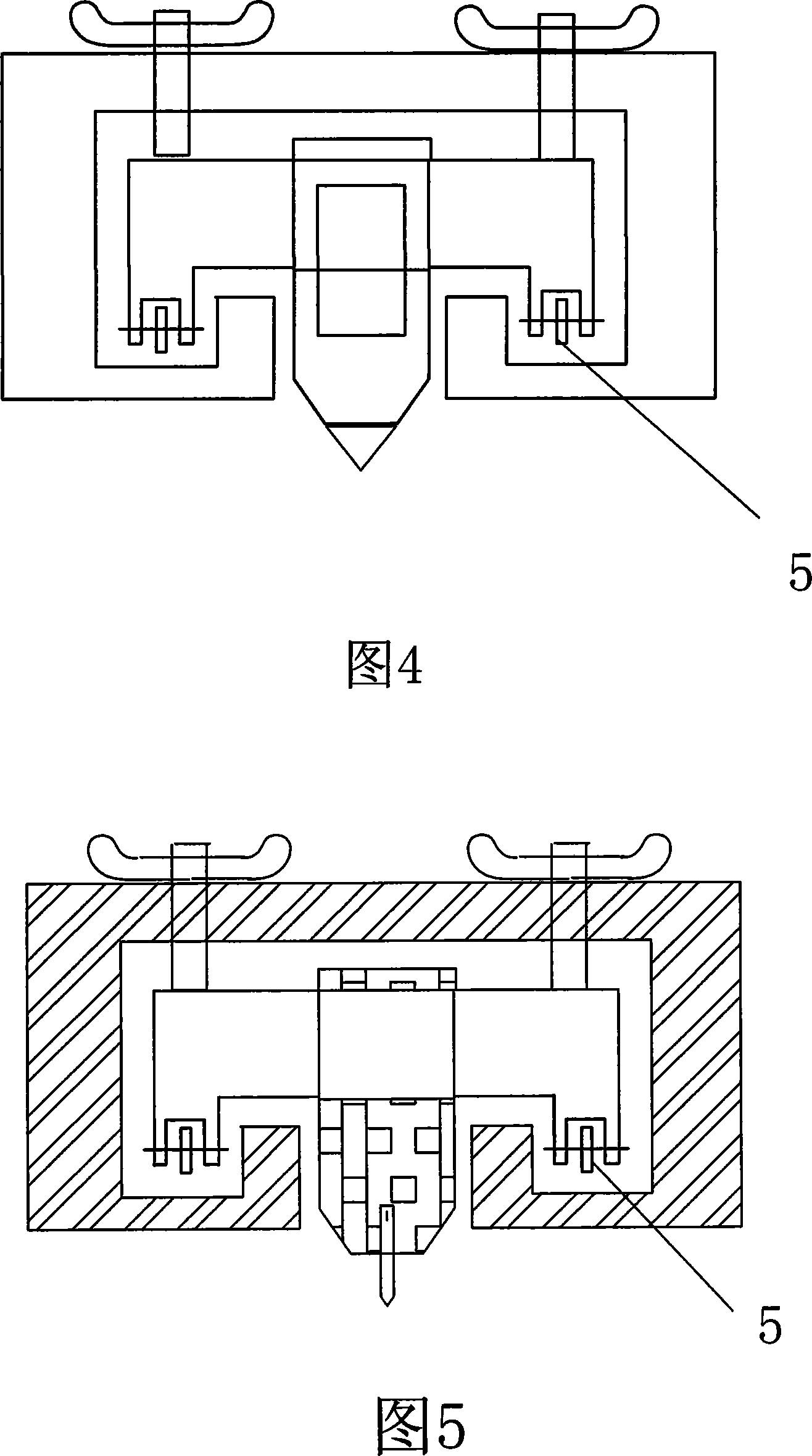
[0042] Second, two pulleys 5 are respectively arranged opposite to the locking bolt 6 on the center of circle slider 2 and the marking slider 3, and two pulleys 5 are respectively provided on both sides of the positioning pin 7, and the both sides of the marking device 4 are also provided with two pulleys 5. Two pulleys 5 are respectively established. In this way, there are four pulleys under each sli...

Embodiment 3

[0044] Embodiment 3 is basically the same structure as Embodiment 2, the difference is:

[0045] A side channel is formed on the side wall of the gauge rod 1, and scales are arranged on both sides of the side channel. Simultaneously, a vertical red line is respectively set on the sides of the center of circle slider 2 and the marking slider 3, and the position of each slider and the distance between the two are precisely determined by the side channel and the red line.


PUM


Abstract

The invention relates to an inner-track gauge used for drawing a big-diameter arc. The structure of the invention mainly comprises a beeline gauge rod provided with an inner groove, a circle-center sliding block which can slide and is embedded in the inner groove and a lineation sliding block which can slide and is embedded in the inner groove. A downwards-through groove towards the inner groove is cut on the bottom wall of the gauge rod. Outer-edge profiles of the circle-center sliding block and the lineation sliding block correspond to the inner edge of the inner groove of the gauge rod. A positioning needle is arranged on the top end of the circle-center sliding block. A lineation device is arranged on the top end of the lineation sliding block. The positioning needle and the lineation device extend from the downwards-through groove. The adoption of the big-size arc positioning lineation device of the invention leads to easy and simple lineation operation, largely enhances the accuracy, and can conveniently complete the lineation of big-size or super-big size arc. The manpower and material resources can be largely conserved and the work efficiency can be largely enhanced.

Description

technical field [0001] The invention relates to a marking tool, in particular to a marking tool for drawing a large circular arc, in particular to an inner rail gauge for drawing a circular arc. Background technique [0002] Large-diameter cylindrical or spherical tanks generally refer to circular containers with a diameter of more than ten meters or even tens of meters, and they are all composed of circular shells. Whether these circular containers are pressure-type or gravity-type, and whether they are double-hull or single-hull, such as gas storage tanks, oil storage tanks and coal storage tanks, because of their large volume and weight, the tank manufacturing equipment brings Very demanding. For these large circular bodies, the existing manufacturing tools cannot meet the use requirements at all, or even if they can meet the use conditions, the manufacturing precision is low, and on the other hand, the operation is complicated and the cost is high. [0003] In the prac...

Claims


Application Information

Patent Timeline
Patent Type & Authority Applications(China)
IPC IPC(8): B25H7/04
Inventor 金戈天刘集善
Owner HUDONG ZHONGHUA SHIPBUILDINGGROUP
Why Eureka
Try Eureka