Storage device and storage system
A storage device and storage medium technology, applied in storage systems, instruments, electrical digital data processing, etc., can solve problems such as inoperability and achieve high reliability and high speed
- Summary
- Abstract
- Description
- Claims
- Application Information
AI Technical Summary
Problems solved by technology
Method used
Image

Examples
Embodiment approach 1
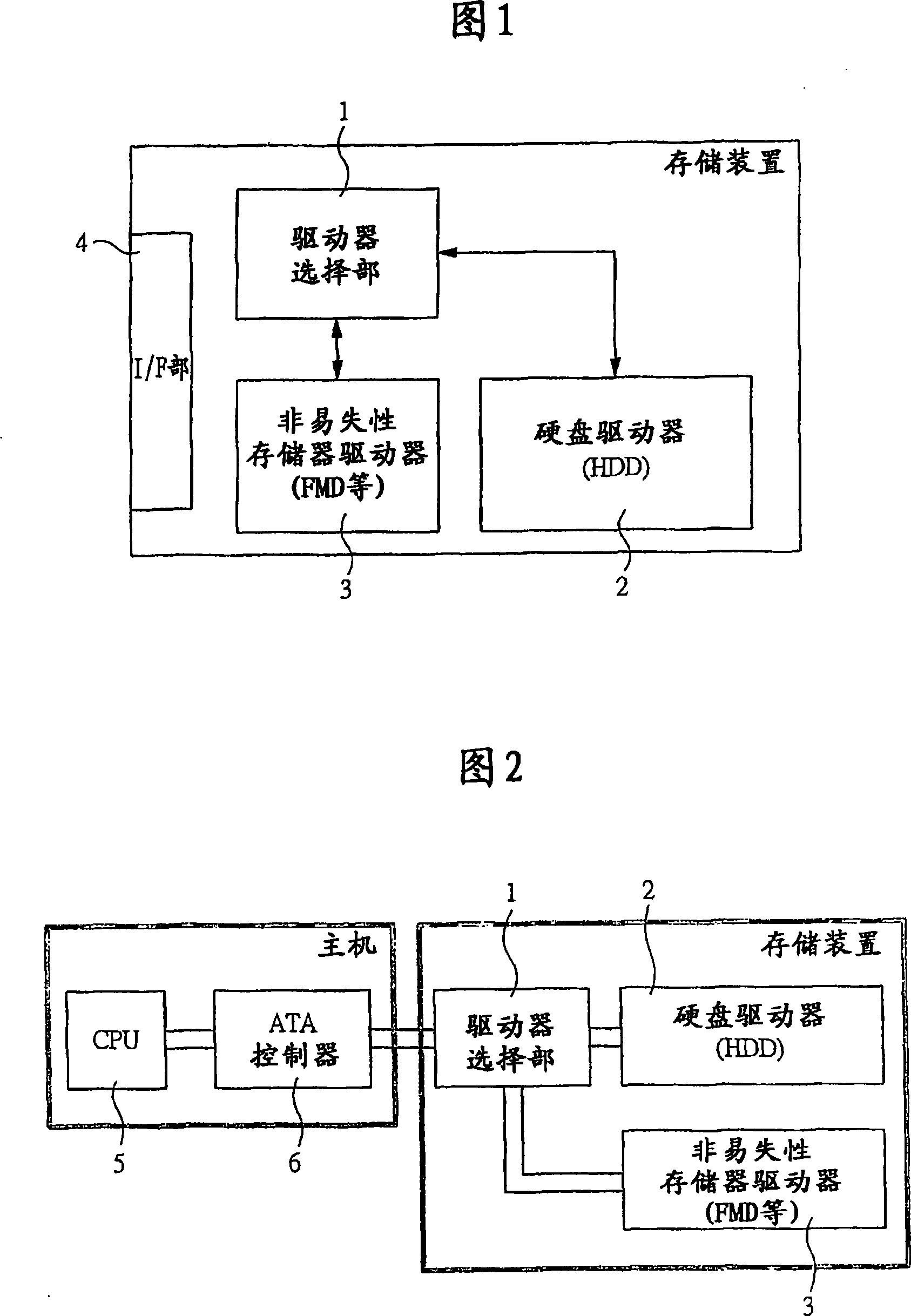
[0048] FIG. 1 is a schematic diagram showing an example of the configuration of a storage device according to Embodiment 1 of the present invention. 2 is a configuration diagram showing an example of a system in which a host is connected to the storage device shown in FIG. 1 in the storage device according to Embodiment 1 of the present invention.
[0049] The storage device shown in FIG. 1 includes, for example, a drive selection unit 1, a hard disk drive (HDD) (first storage device) 2, a nonvolatile memory drive (second storage device) 3 such as a flash memory drive (FMD), and The interface (I / F) part 4 etc. are comprised. In addition, in FIG. 2 , the interface unit 4 of the storage device is configured such that a host computer composed of, for example, a CPU 5 and an ATA (AT Attachment) controller 6 is connected.
[0050] The above-mentioned hard disk drive (HDD) 2 has a magnetic storage medium and a controller for controlling the magnetic storage medium inside, and its c...
Embodiment approach 2
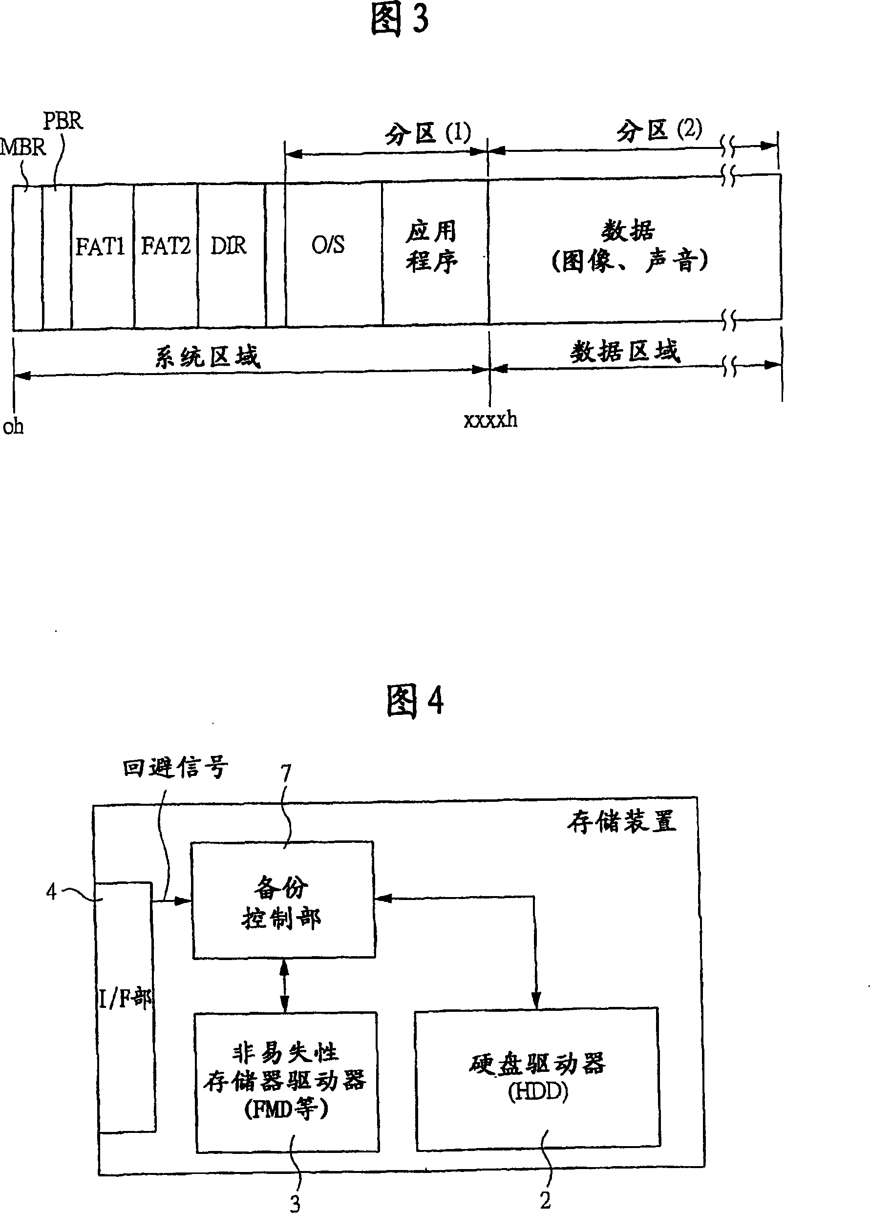
[0062] FIG. 4 is a schematic diagram showing an example of the configuration of the storage device according to Embodiment 2 of the present invention. The storage device shown in FIG. 4 includes, for example, a backup control unit 7, a hard disk drive (HDD) 2, a nonvolatile memory drive 3 such as a flash memory drive (FMD), an interface unit 4, and the like.
[0063] The configuration other than the above-mentioned backup control unit 7 is the same as that of FIG. 1 above, so description thereof will be omitted. The above-mentioned backup control unit (the second control unit) 7 has a avoidance signal as an input signal, and has the following function: when the above-mentioned avoidance signal is input, a part of data in the above-mentioned hard disk drive (HDD) 2 is extracted and transferred to the nonvolatile memory. The memory driver 3 transfers the extracted data. In addition, conversely, there is also a function of transferring data stored in the nonvolatile memory drive...
Embodiment approach 3
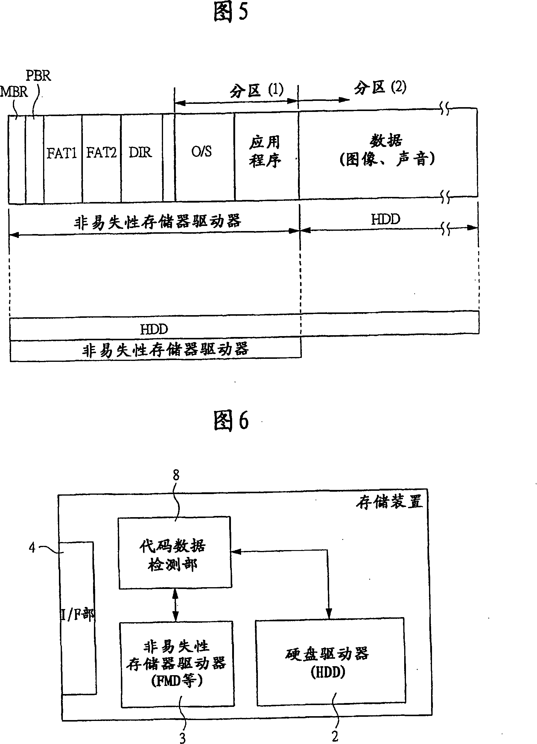
[0068] FIG. 6 is a schematic diagram showing an example of the configuration of the storage device according to Embodiment 3 of the present invention. The storage device shown in FIG. 6 includes, for example, a code data detection unit 8, a hard disk drive (HDD) 2, a nonvolatile memory drive 3 such as a flash memory drive (FMD), an interface unit 4, and the like.
[0069] The configuration other than the above code data detection unit 8 is the same as that of FIG. 1 above, so the description thereof will be omitted. The above-mentioned code data detecting unit (second control unit) 8, for example, as shown in FIG. Error code, Error Correcting Code) and other error detection and correction code data, only the part of the code data is extracted, and the data is stored in the above-mentioned nonvolatile memory driver 3.
[0070] In addition, when a data output command is issued from the host computer to the hard disk drive (HDD) 2, the code data detection unit outputs the data o...
PUM
 Abstract
Description
Claims
Application Information