
Traffic control method, system and device

A flow control and flow technology, applied in the field of data communication, can solve the problems of insufficient egress bandwidth, unreasonable bandwidth allocation, excessive egress bandwidth, etc., and achieve the effect of improving rationality and avoiding unreasonable resource allocation.

Active Publication Date: 2008-05-28
新华三半导体技术有限公司
View PDF0 Cites 26 Cited by
  • Summary
  • Abstract
  • Description
  • Claims
  • Application Information

AI Technical Summary

Problems solved by technology

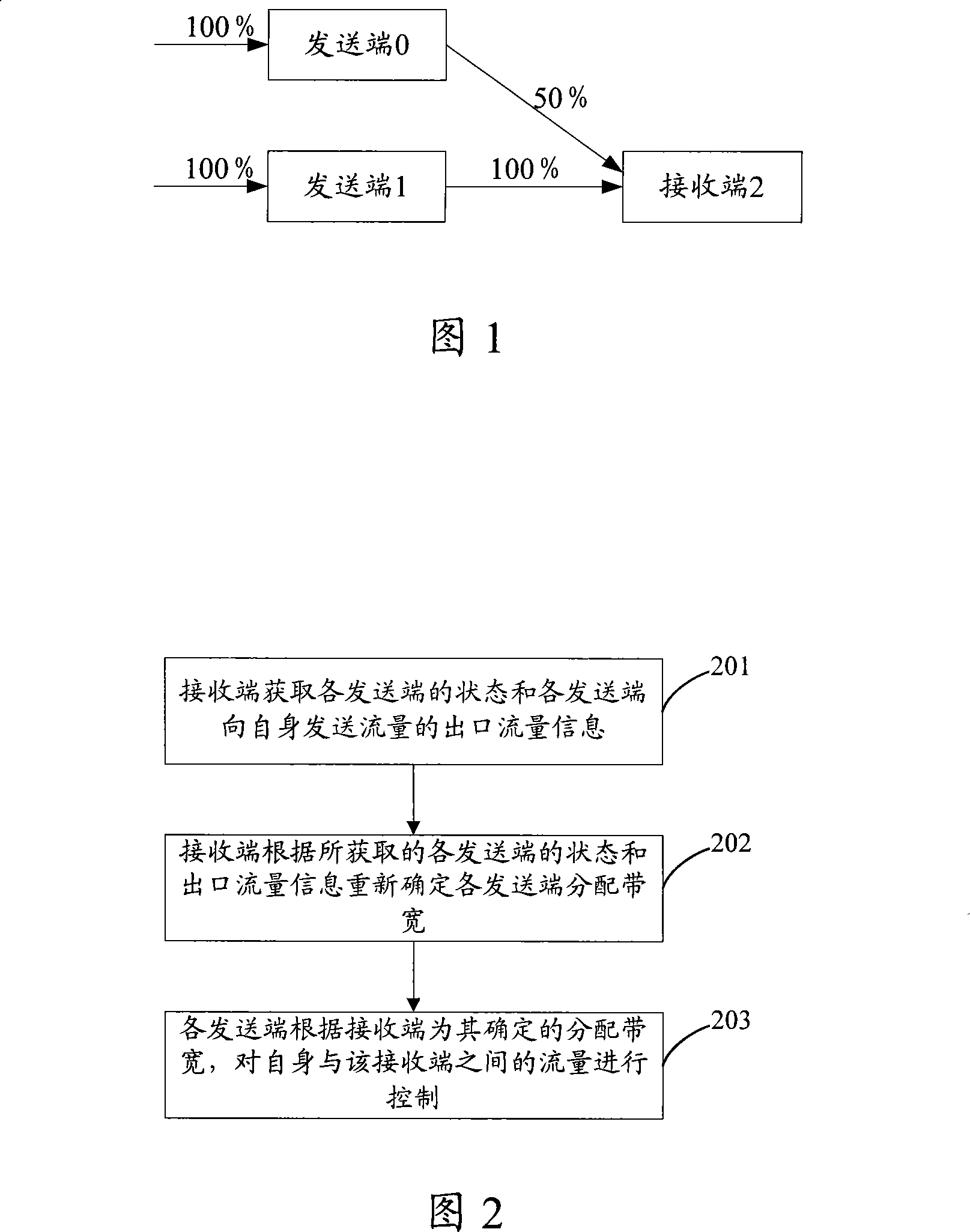
However, if the actual egress traffic of sender 0 is very large and the actual egress traffic of sender 1 is very small, then the egress bandwidth allocated to sender 0 is insufficient, while the egress bandwidth allocated to sender 1 is excessive
[0004] It can be seen that the existing flow control mechanism adopts the same control granularity for each sending end, which makes the bandwidth allocation in the distributed switching system unreasonable, resulting in unreasonable utilization of bandwidth resources

Method used


Image

  • Traffic control method, system and device
  • Traffic control method, system and device
  • Traffic control method, system and device

Examples


Embodiment Construction

[0043] The present invention will be described in detail below with reference to the accompanying drawings and examples.

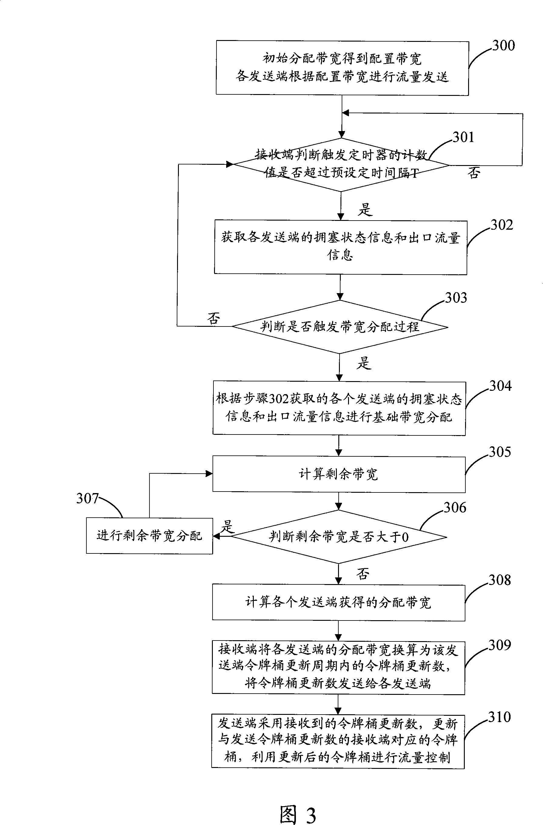
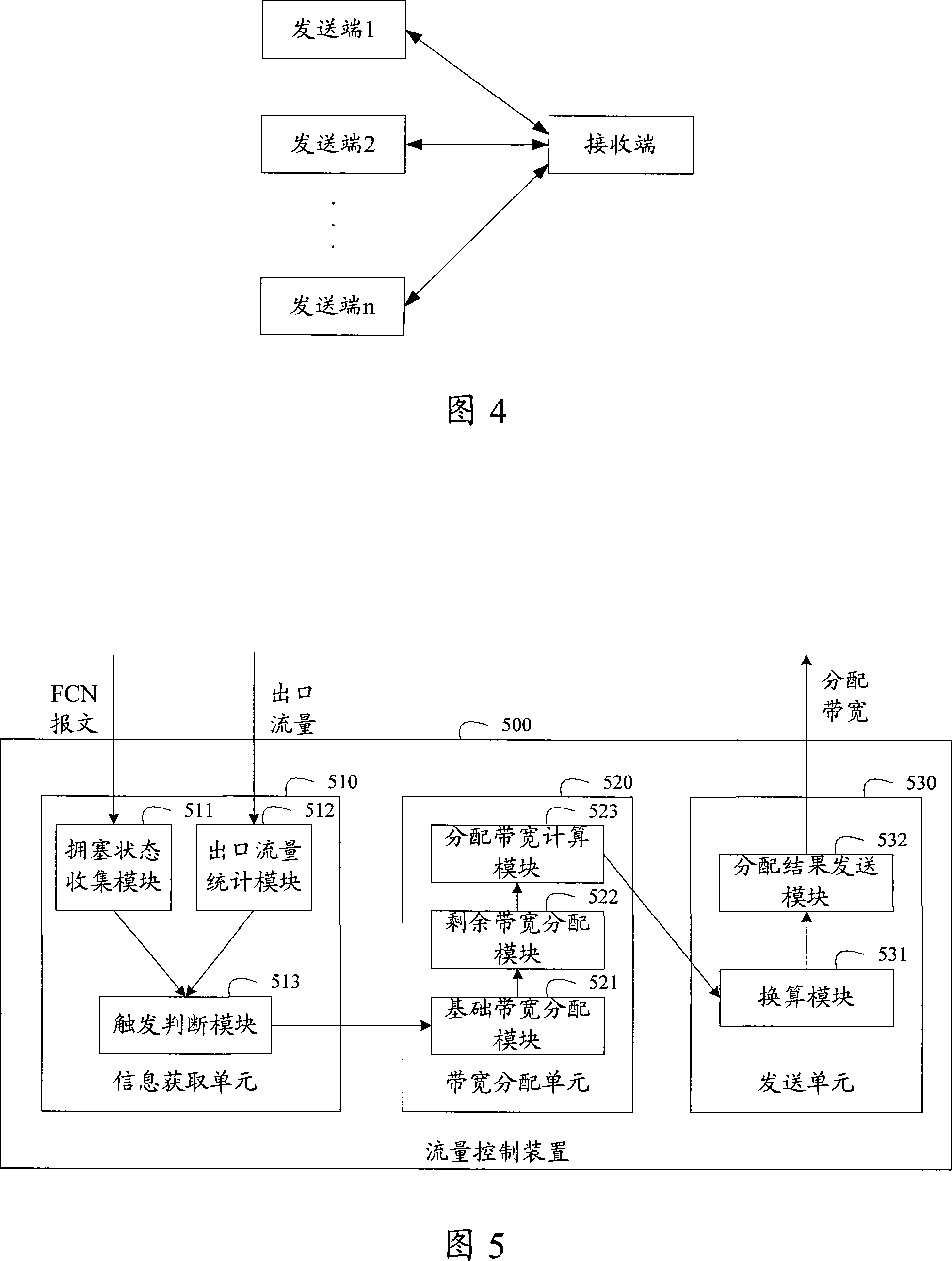
[0044] The present invention is a flow control scheme, the basic idea of ​​which is: in a distributed switching system, the receiving end allocates bandwidth (Alloband, Allocation bandwidth) for each sending end according to the state and egress flow information of each sending end, and each sending end allocates bandwidth (Allocation bandwidth) for each sending end according to the receiving end The end-end allocates bandwidth for it, and controls the flow between itself and the receiving end, thereby improving the rationality of bandwidth allocation and making reasonable use of bandwidth resources.

[0045] Wherein, the allocated bandwidth refers to the egress bandwidth obtained by each sending end after flow control.

[0046] Fig. 2 shows an exemplary flowchart of a flow control scheme based on the above basic idea, as shown in Fig. 2, the method includ...


PUM


Abstract

The invention discloses a flow controlling method, which is used in a distributed exchange system. The method includes the steps that a receiving terminal receives status and outgoing flow information of each sending terminal, the receiving terminal determines the distributed band width of each sending terminal according to the status and outgoing flow information received; and each sending terminal controls the flow between the self and the receiving terminal according to the distributed band width determined by the receiving terminal. The invention discloses further a flow controlling system and a flow controlling device. By use of the invention, rationality of the band width distribution can be improved, thus the band width resource can be fully and rationally utilized.

Description

technical field [0001] The invention relates to the field of data communication, in particular to a flow control method, a flow control system and a flow control device applied to a distributed switching system. Background technique [0002] In the communication process, in order to prevent user traffic congestion, flow control technology is usually used to control network traffic. The basic principle of the existing flow control mechanism is: if the receiving end of the traffic is congested, the receiving end sends a control frame to notify the sending end to slow down the sending speed to alleviate the congestion. [0003] However, the above-mentioned flow control mechanism is generally aimed at a one-to-one communication situation in which one sending end corresponds to one receiving end. However, in a distributed switching system, it often occurs that multiple senders send traffic to one receiver, and one sender sends traffic to multiple receivers. FIG. 1 shows a schem...

Claims


Application Information

Patent Timeline
Patent Type & Authority Applications(China)
IPC IPC(8): H04L12/56H04L47/20H04L47/76
Inventor 赵广张德宁邓新红
Owner 新华三半导体技术有限公司
Learn More